
Remote Control Circuit
Index 20
The application circuit of infrared controller CW168
Published:2011/6/30 4:11:00 Author:Seven | Keyword: application circuit, infrared controller
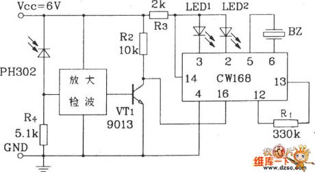
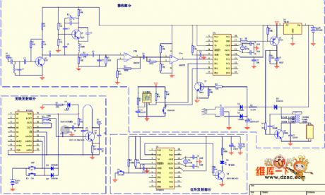
The figured infrared receiver receives the 38KHz modulation signal from the emitter, and the signal is sent to the basic pole of VT1 after it is magnified and rectified, so VT1 is saturated and conducting, CW168 is triggered to work. The circuit can complete single or continuous working way and tone selection.
(View)
View full Circuit Diagram | Comments | Reading(1034)
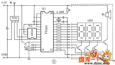
The constant temperature control circuit of the developing solution
Published:2011/6/30 20:19:00 Author:qqtang | Keyword: temperature control circuit, developing solution
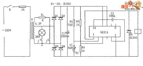
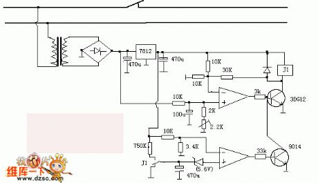
In the figure is the constant temperature control circuit of the developing solution. This circuit consists of the step-down rectifier power supply circuit(B, D1~D4, C1 and so on), temperature detecting bridge R3~R4, voltage comparing amplifier and power output circuit 5G31, relay J, load RL and so on, of which R3 has the same resistance with R4, and they are linked to the passive input terminal as the Vref. R2 is a thermistor, R1 is the temperature adjusting resistor, RL is the loading resistor(heater) and 5G31 is the audio power amplifier.When the power is on, the temperature is low and the resistance of R1 is high.
(View)
View full Circuit Diagram | Comments | Reading(996)
555 simple color TV additional remote control circuit
Published:2011/6/15 22:07:00 Author:TaoXi | Keyword: 555, simple, color TV, additional remote control
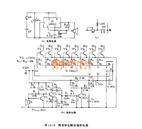
The color TV additional circuit is as shown in figure 14-16. The astable multivibrator is composed of the 555 and R2, RP, C2, the oscillation frequency is decided by the RP, R2, C2. The receiving circuit is composed of the amplifier circuit, the rectifier circuit and the counting circuit, the CD4017 is a decimal count / pulse distributor integrated circuit. When the CD4017 receives the control signal, the Q0~Q7 successively outputs the high level to control the conduction and cut-off of the VT4~VT11 transistors, and it also controls the on-off of the color TV's primary switch. In figure (b), the collector electrodes of VT4~VT11 are connected with the 1-8 connection points of the manual control preliminary selection button, such as the point A of figure (c).
(View)
View full Circuit Diagram | Comments | Reading(1300)
The 8-line remote control emitter(CS901) circuit
Published:2011/6/27 20:54:00 Author:Borg | Keyword: 8-line, remote control emitter
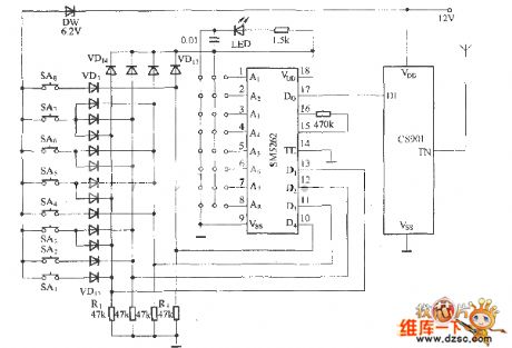
In the figure is the 8-line remote control emitter which is composed of the CS901 module and the digital encoder SM5262 (the same with PT2262), the keys SA1~SA8 and diodes VD1~VD13 compose the 8-line matrix input circuit as the encoding input circuit of the emitter. As the 7~13 pins of SM5262 are the address/data sharing terminals, if they are regarded as the data input terminal, the circuit will have 6 data input terminals in total, when all their functions are taken as the data input, they can compose the 26=64, i.e the 64-way, remote control emitter. In the circuit, only 4 terminals of D1~D4 are put in use.
(View)
View full Circuit Diagram | Comments | Reading(4039)
555 stereo audio equipment remote controller circuit
Published:2011/6/15 18:55:00 Author:TaoXi | Keyword: 555, stereo, audio equipment, remote controller

As the figure 14-8 shows, the remote controller is composed of the infrared ray coding emitter and the infrared ray decoding receiver. Figure (a) shows the 5-channel infrared coding emitter circuit. The astable multivibrator is composed of the 555 and C1, R6, R1 ~ R5, the oscillation frequency f=1.44/(R1-5+2R6)C1, the five channels are 10kHz,15kHz,20kHz,25kHz and 30kHz. The IC2 is the quad 2-input port NAND gate, the controlled oscillator is composed of the D1 and D2, the oscillation frequency f0=1/(1.4~2.2)RP1C3, f0 of the figure is about 38 to 40kHz. The infrared ray transmitting tube uses the SE303A or the HG4100 series tube. The receiver decoding circuit is composed of the infrared receiver tube, the special decoding circuit, the 5-channel single-tone decoder, the counting circuit and the stereo control circuit.etc.
(View)
View full Circuit Diagram | Comments | Reading(1216)
A self-recovery over-voltage protection circuit
Published:2011/6/28 0:22:00 Author:Borg | Keyword: self-recovery, over-voltage, protection circuit
View full Circuit Diagram | Comments | Reading(943)
Infrared remote control energy-saving lamp circuit diagram
Published:2011/6/27 3:53:00 Author:Ecco | Keyword: Infrared, remote control, energy-saving lamp
View full Circuit Diagram | Comments | Reading(2384)
The long-span timing circuit
Published:2011/6/24 21:32:00 Author:qqtang | Keyword: long-span, timing
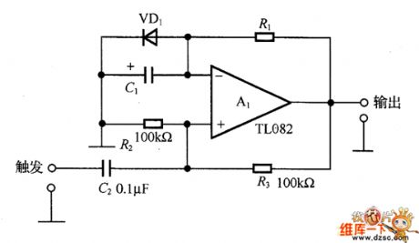
In the circuit is the long-span timing circuit. In the circuit, A1 is a FET input op-amp TL082, the voltage on the non-inverting is half of the saturating voltage(about 12V), and the voltage of the inverting terminal is fixed at +.0.6V due to the conduction of VD1. If the triggering terminal is input with a higher than 6V passive pulse, A1 is in passive saturation, at the moment, the non-inverting terminal is in a -6V voltage, the capacitor C1 is charging back with the help of R1, is the charging voltage is over -0.6, A1 output is in positive saturation, then a period is over. The charging time is T=R1C1ln(R2+R3)/R3.
(View)
View full Circuit Diagram | Comments | Reading(887)
The time delay circuit composed of transistors and comparators
Published:2011/6/24 22:55:00 Author:qqtang | Keyword: time delay, transistors, comparators
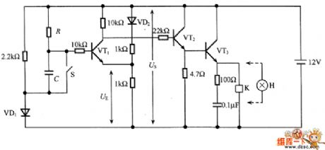
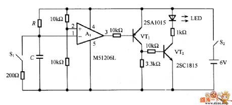
In Figure 2 is the time delay circuit composed of transistors and comparators. The circuit is like the circuit that is shown in Figure 1, the comparing circuit is the comparator integrated chip M51206l, which is not affected by the environment temperature change and power supply voltage change, therefore, it's stable. If VT2 is made of the Darlington power transistor, the circuit can drive large current loading.
Figure 1
Figure 2 (View)
View full Circuit Diagram | Comments | Reading(2116)
BA5201 remote control decoding integrated circuit
Published:2011/6/21 0:53:00 Author:Christina | Keyword: remote control, decoding, integrated circuit
The BA5201 is designed as one kind of remote control decoding integrated circuit that is produced by the Toyo company, and it can be used in various types of remote control systems.
1.Pin functions and data
The BA5201 integrated circuit is in the 16-pin dual-row DIP package, the pin functions and data is as shown in table 1.
Table 1 The pin functions and data of the BA5201
2.Typical application circuit
The typical application circuit of the decoding system which is composed of the BA5201 is as shown in figure 1.
Figure 1 The typical application circuit of the BA5201
(View)
View full Circuit Diagram | Comments | Reading(1410)
BA5102 remote control encoding integrated circuit
Published:2011/6/21 1:49:00 Author:Christina | Keyword: remote control, encoding, integrated circuit
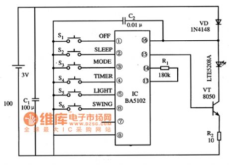
The BA5102 is designed as one kind of remote control encoding integrated circuit that is produced by the Toyo company, and it can be used in various types of electric fan's remote control transmitters.
1.Pin functions and data
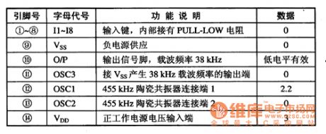
The BA5102 integrated circuit is in the 16-pin dual-row DIP package, the pin functions and data is as shown in table 1.
Table 1 The pin functions and data of the BA5102
2.Typical application circuit
The typical application circuit of the remote control transmitter which is composed of the BA5102 is as shown in figure 1.
Figure 1 The typical application circuit of the remote control transmitter which is composed of the BA5102
(View)
View full Circuit Diagram | Comments | Reading(1438)
BA5101 remote control encoding integrated circuit
Published:2011/6/21 1:55:00 Author:Christina | Keyword: remote control, encoding, integrated circuit
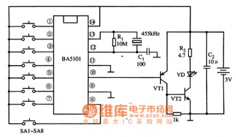
The BA5101 is designed as one kind of remote control encoding integrated circuit that is produced by the Toyo company, and it can be used in various types of electric fan's program control remote control systems.
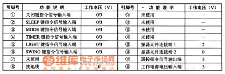
1.Pin functions and data
The BA5101 integrated circuit is in the 14-pin dual-row DIP package, the pin functions and data is as shown in table 1.
Table 1 The pin functions and data of the BA5101
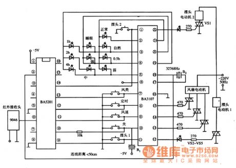
2.Typical application circuit
The BA5101 integrated circuit can be used with the BA5201, BA3107, infrared receiver LTM49046, the coding transmission system typical application circuit which is composed of the BA5101 is as shown in figure 1.
Figure 1 The typical application circuit of BA5101 integrated circuit
(View)
View full Circuit Diagram | Comments | Reading(1858)
The time delay circuit of dual-way transistors
Published:2011/6/25 5:25:00 Author:qqtang | Keyword: time delay circuit, dual-way transistors
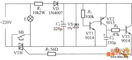
In the figure is the time delay circuit of dual-way transistors. Apart from the values of C1, C2 and R4, the timing is also relevant to the time of pressing the key. VTH can be the dual-way transistors of MAC94A4 and MAC97A6, and the β values of both VT1 and VT2 should be larger than 200.
(View)
View full Circuit Diagram | Comments | Reading(1182)
BA5104 remote control transmitter integrated circuit
Published:2011/6/21 1:01:00 Author:Christina | Keyword: remote control, transmitter, integrated circuit
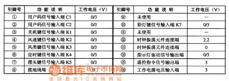
The BA5104 is designed as one kind of remote control transmitter integrated circuit that is produced by the Toyo company, and it can be used in various types of remote control transmitters.
1.Pin functions and data
The BA5104 integrated circuit is in the 16-pin dual-row DIP package, the pin functions and data is as shown in table 1.
Table 1 The pin functions and data of the BA5104
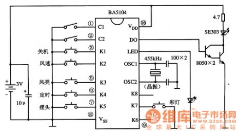
2.Typical application circuit
The typical application circuit of the remote controller which is composed of the BA5104 is as shown in figure 1.
Figure 1 The typical application circuit of the remote controller which is composed of the BA5104
(View)
View full Circuit Diagram | Comments | Reading(5035)
The color TV remote control 20 circuit
Published:2011/6/23 22:09:00 Author:Seven | Keyword: color TV, remote control
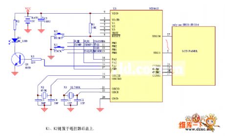
Figure: The color TV remote control 20 circuit (View)
View full Circuit Diagram | Comments | Reading(1237)
The color TV remote control circuit (19)
Published:2011/6/23 22:14:00 Author:Seven | Keyword: color TV, remote control
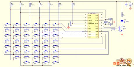
Figure: The color TV remote control circuit (19) (View)
View full Circuit Diagram | Comments | Reading(2401)
The color TV remote control circuit (18)
Published:2011/6/23 22:21:00 Author:Seven | Keyword: color TV, remote control
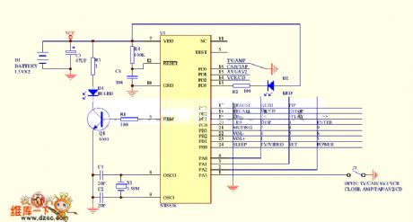
Figure: The color TV remote control circuit (18) (View)
View full Circuit Diagram | Comments | Reading(1013)
The color TV remote control circuit (17)
Published:2011/6/23 22:23:00 Author:Seven | Keyword: color TV, remote control
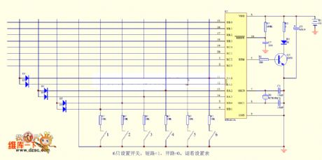
Figure: The color TV remote control circuit (17) (View)
View full Circuit Diagram | Comments | Reading(1874)
The color TV remote control circuit (16)
Published:2011/6/23 22:26:00 Author:Seven | Keyword: color TV, remote control
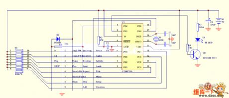
Figure: The color TV remote control circuit (16) (View)
View full Circuit Diagram | Comments | Reading(1084)
The multi-way wireless remote control receiving host circuit
Published:2011/6/23 19:59:00 Author:Seven | Keyword: multi-way, wireless, remote control
In the circuit, when the high frequency receiving component T932 receives the wireless encoding signal from the emitter, after being rectified by the pulse circuit, 2-pin of T932 outputs the restored address code, crossing code, digit code, clock code and other signals, the signal is added on the 10-pin of PT2243, and after it is confirmed by the internal dynamic state decoding scanner, the signal is output from the according connector as a 3-bit digit decoding signal, which can drive 3-bit 7-stage LED screen. The circuit can be connected with other circuit for the user, such as PC management. (View)
View full Circuit Diagram | Comments | Reading(1243)
| Pages:20/34 1234567891011121314151617181920Under 20 |
Circuit Categories
power supply circuit
Amplifier Circuit
Basic Circuit
LED and Light Circuit
Sensor Circuit
Signal Processing
Electrical Equipment Circuit
Control Circuit
Remote Control Circuit
A/D-D/A Converter Circuit
Audio Circuit
Measuring and Test Circuit
Communication Circuit
Computer-Related Circuit
555 Circuit
Automotive Circuit
Repairing Circuit