
Automotive Circuit
Index 93
Shanghai GM Buick LaCROSSE Car 2.4L Engine Circuit (9)
Published:2011/5/9 5:55:00 Author:Robert | Keyword: Shanghai GM, Buick, LaCROSSE, 2.4L Engine

The Shanghai GM Buick LaCROSSE Car 2.4L Engine Circuit (9) is shown below.
(View)
View full Circuit Diagram | Comments | Reading(508)
Shanghai GM Buick LaCROSSE Car 2.4L Engine Circuit (10)
Published:2011/5/9 5:54:00 Author:Robert | Keyword: Shanghai GM, Buick, LaCROSSE, 2.4L Engine
The Shanghai GM Buick LaCROSSE Car 2.4L Engine Circuit (10) is shown below.
(View)
View full Circuit Diagram | Comments | Reading(527)
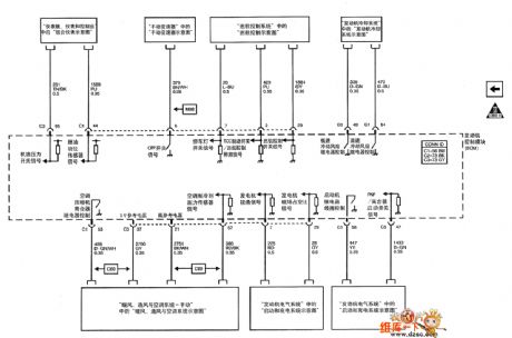
Shanghai GM Buick LaCROSSE Car 2.4L Engine Circuit (35)
Published:2011/5/9 5:54:00 Author:Robert | Keyword: Shanghai GM, Buick, LaCROSSE, 2.4L Engine

The Shanghai GM Buick LaCROSSE Car 2.4L Engine Circuit (35) is shown below.
(View)
View full Circuit Diagram | Comments | Reading(514)
Mitsubishi Pajero (PAJERO) brand light off-road vehicle radio and clock principle circuit diagram
Published:2011/5/8 11:31:00 Author:Rebekka | Keyword: Mitsubishi Pajero , light off-road vehicle
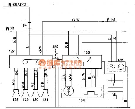
Mitsubishi Pajero (PAJERO) brand light off-road vehicle radio and clock principle circuit diagram.
68 fire switch; 127 radio; 128,129 front left and right speakers; 130,131 rear left and right speakers; 132 automatic antenna switch; 133 automatic antenna controller; 134 automatic antenna motor; 135 Clock (View)
View full Circuit Diagram | Comments | Reading(1300)
Mitsubishi Pajero (PAJERO) brand light off-road vehicle general instrument and the ignition lock illumination timing principle diagram
Published:2011/5/8 12:11:00 Author:Rebekka | Keyword: Mitsubishi Pajero (PAJERO) , light off-road vehicle

Mitsubishi Pajero (PAJERO) brand light off-road vehicle general instrument and the ignition lock illumination timing principle diagram.
136 magnetic sensor; 137 generic instrument; 138 thermal sensor inside the air; 139 car air thermal sensor; 140 ignition switch lighting timer; 141 switch that lights the fire; 142 front door switche.
(View)
View full Circuit Diagram | Comments | Reading(1041)
Ling Pajie years (PAJERO) light off-road vehicle central control door lock set circuit diagram
Published:2011/5/8 11:37:00 Author:Rebekka | Keyword: Ling Pajie years , light off-road vehicle, central control door lock set

Ling Pajie years (PAJERO) light off-road vehicle central control door lock set circuit diagram.
15 lock controller; 16 passenger-side door lock switch; 17 the driver's side door of motor; 18 passenger-side door lock motor; 19 left rear door lock motor; 20 one right after the door lock motors; 21 after the door of motor; 22 auxiliary socket relay; 23 auxiliary socket; 127 Shoufang Ji (View)
View full Circuit Diagram | Comments | Reading(952)
Zhengzhou NISSAN PALDIN car air conditioning system circuit diagram
Published:2011/5/9 21:47:00 Author:Nicole | Keyword: Zhengzhou NISSAN, PALDIN, car, air conditioning system
View full Circuit Diagram | Comments | Reading(691)
The Ignition Circuit of Santana(32MP003182 chassis)
Published:2011/5/10 2:50:00 Author:Borg | Keyword: Ignition CircuitS, antana
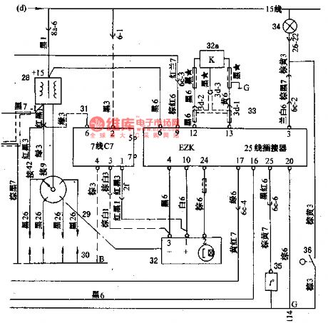
As shown in Figure 1 is that the signal voltage produced by the Hall signal generator (32) of the ignition system is sending to the igniting control unit(EZK) (33), the unit will deliver igniting signals in time according to this signal and signals of explosion sensor 32a, engine coolant temperature signals of thermometer(35) and by computing, this signal is delivered from the points (16 and 17) of EZK to points(15 and 20) of LE-Jetronic, by which the breaking time and the dwell angle controling the elementary circuit is under control, then the sub-coils generate high voltage which is delivered to each cylinder piston(30) by electricity distractors(29).
In the figure, there is also a ignition control module (31) which is connected with the Hall signal generator and igniting coils by a dotted line, this is a stand-by project. If there weren’t the petrol jet control unit(24) and igniting control unit(33), the ignition circuit would be like Santana LX, GX,etc. (View)
View full Circuit Diagram | Comments | Reading(656)
Great Wall Pick Up Car air conditioning system control circuit diagram
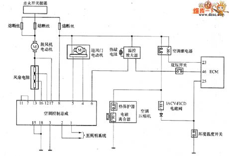
Published:2011/5/9 21:59:00 Author:Nicole | Keyword: Great Wall, Pick Up Car, air conditioning system
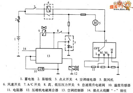
1. storage battery; 2. fusible line; 3. ignition switch; 4. air conditioner relay; 5. blower; 6. air velocity switch; 7. A/C switch; 8. high, low pressure switch; 9. idle speed promotion electromagnetic valve; 10. temperature sensor; 11. resistor; 12. compressor electromagnetic clutch; 13. air conditioner controller; 14. connecting with ignition coil - bracket. (View)
View full Circuit Diagram | Comments | Reading(2708)
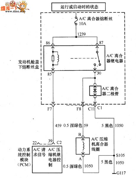
GM BUICK GL8 commercial vehicle air conditioner compressor control circuit diagram
Published:2011/5/9 22:04:00 Author:Nicole | Keyword: GM BUICK, commercial vehicle, air conditioner, compressor
View full Circuit Diagram | Comments | Reading(654)
TA8493F spindle three-phase motor driver integrated circuit
Published:2011/5/8 5:34:00 Author:TaoXi | Keyword: spindle, three-phase, motor driver
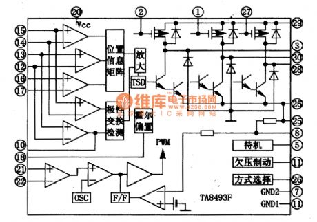
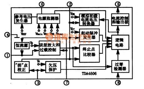
The TA8493F is designed as one kind of spindle three-phase motor driver integrated circuit that is produced by the TOSHIBA company, and this device can be used in DVD player as the dedicated driver circuit.
1. In-circuit block diagram
The TA8493F has the Hall position signal matrix circuit, the polarity reversal detection circuit, the differential amplifier & 3 phases motor driver circuit, and the mode selection & undervoltage braking circuit. The in-circuit block diagram is as shown in figure 1.
Figure 1 The in-circuit block diagram of the TA8493F
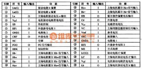
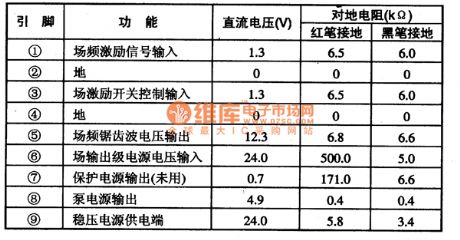
2.Pin functions
The TA8493F is in the 30-pin package, the pin dunctions and data is as shown in table 1.
Table 1 The pin functions and data of the TA8493F (View)
View full Circuit Diagram | Comments | Reading(723)
TA8445K field scanning output integrated circuit
Published:2011/5/8 5:47:00 Author:TaoXi | Keyword: field scanning, output
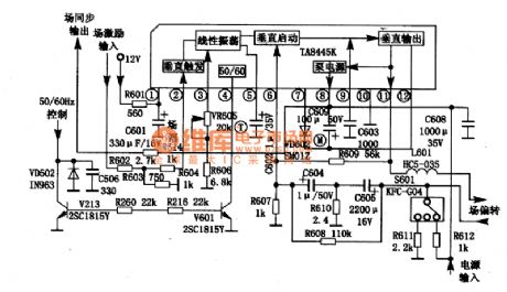
The TA8445K field scanning output integrated circuit is produced by the TOSHIBA company, and it can be used in variety kinds of domestic and imported TVs.
1.Features
The TA8445K has the acoustic excitation output circuit, the pump power supply circuit, the field oscillation and sawtooth production circuit. The maximum output current is 2.2Ap-p, the maximum output power is 12.5W. The in-circuit block diagram and the typical application circuit of the TA8445K are as shown in figure 1.
Figure 1 The in-circuit block diagram and the typical application circuit of the TA8445K
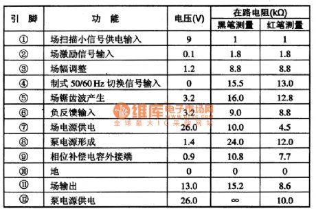
2.Pin functions and data
The pin functions and data of the TA8445K is as shown in table 1.
Table 1 The pin functions and data of the TA8445K (View)
View full Circuit Diagram | Comments | Reading(3480)
TDA3653B, TDA3653C, TDA3654B--Field scanning output integrated circuit
Published:2011/5/8 6:46:00 Author:TaoXi | Keyword: Field scanning, output
The TDA3653B, TDA3653C, TDA3654B--Field scanning output integrated circuit is produced by the PHILIPS company that can be used in domestic and imported color television sets.
The TDA3653B and TDA3653C's maximum output current is 1.5Ap.P, the maximum output power is 8W; the TDA3653B's maximum output current is 2.2Ap.P, the maximum output power is 15W. They have the same pin functions. The typical application circuit of the integrated block is as shown in figure 7, and the pin functions and data is as shown in table 9. The data is from the TDA3653B in Changhong C2191 TV.
Table 9 The pin functions and data of the TDA3653B/C and TDA3654B
(View)
View full Circuit Diagram | Comments | Reading(3592)
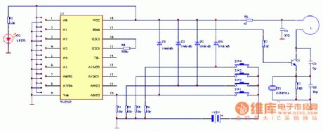
Key Ring Wireless Encoding Remote Controller Circuit (2)
Published:2011/5/9 5:10:00 Author:Sue | Keyword: Key Ring, Wireless, Encoding, Remote Controller
As seen in the figure is the key ring wireless encoding remote controller circuit. (View)
View full Circuit Diagram | Comments | Reading(532)
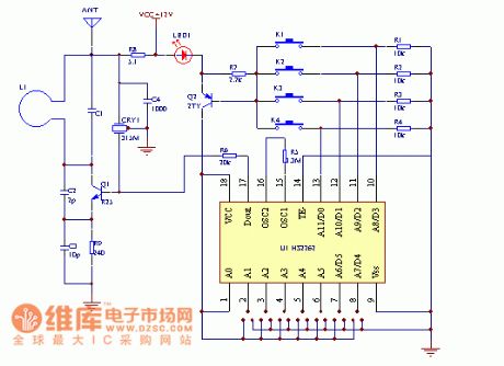
Key Ring Wireless Encoding Remote Controller Circuit (1)
Published:2011/5/9 5:11:00 Author:Sue | Keyword: Key Ring, Wireless, Encoding, Remote Controller
As seen in the figure is the key ring wireless encoding remote controller circuit. (View)
View full Circuit Diagram | Comments | Reading(493)
Infrared Circuit Principle Diagram
Published:2011/5/9 5:12:00 Author:Sue | Keyword: Infrared, Principle Diagram
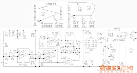
As seen in the figure is the infrared circuit principle diagram. (View)
View full Circuit Diagram | Comments | Reading(565)
Automatical wiper control system circuit diagram
Published:2011/5/9 20:48:00 Author:Nicole | Keyword: aAutomatical wiper, control system
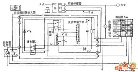
It is a automatical wiper control system circuit diagram, when the rain drops to sensor, its internal will produce voltage(A point) change which changes in relation to the rain intensity and frequency(in piezoelectric element, the voltage waveform is proportional to the rain drop energy), this voltage waveform is amplified by sensor internal amplifier circuit(B point), it is stored in power amplifier charge circuit. When the voltage singal of storing charge circuit reaches a definite value(V0), it is imported into wiper dirve circuit by comparing circuit, then the wiper starts to work.
The interval time(T) is proportional to the speed 14 of charge circuit voltage, so the wiper's energy is higher, the car speed is quicker, so the time is shorter; on the contrary, the time is longer.
(View)
View full Circuit Diagram | Comments | Reading(1095)
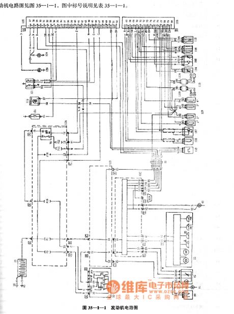
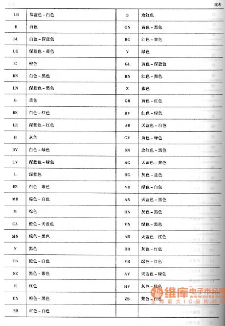
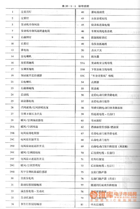
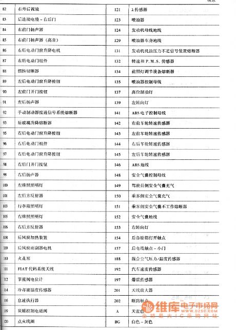
Fiat Palio motor circuit diagram
Published:2011/5/9 21:18:00 Author:Ecco | Keyword: Fiat Palio, motor
View full Circuit Diagram | Comments | Reading(4508)
Spread Spectrum Rolling code Wireless Tracking Alarm Components KB318/KB318R
Published:2011/5/9 10:22:00 Author:TaoXi | Keyword: Spread Spectrum, Rolling code, Wireless Tracking, Alarm Components
The spread spectrum rolling code wireless tracking alarm component can be used in the situations that need the long distance wireless BP machine type feedback alarm such as the cars, motorcycles and other, it uses the advanced technology and devices, so it has the perfect functions and is better than other similar products. The spread spectrum rolling code wireless tracking alarm component is composed of a wireless transmitter KB318T (or KB923T), and a key buckle type micro receiving alarm KB318R (or KB923R). The remote control transmitter principle figure is as shown: (View)
View full Circuit Diagram | Comments | Reading(508)
TDA16846 pin functions and data circuit
Published:2011/5/8 22:25:00 Author:TaoXi | Keyword: pin functions, data
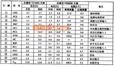
2.Pin functions and data
The TDA16846 can be used in the Konka series TV, and the pin functions and data is as shown in table 61.
Table 61 The pin functions and data of the TDA16846
(View)
View full Circuit Diagram | Comments | Reading(1226)
| Pages:93/164 At 2081828384858687888990919293949596979899100Under 20 |
Circuit Categories
power supply circuit
Amplifier Circuit
Basic Circuit
LED and Light Circuit
Sensor Circuit
Signal Processing
Electrical Equipment Circuit
Control Circuit
Remote Control Circuit
A/D-D/A Converter Circuit
Audio Circuit
Measuring and Test Circuit
Communication Circuit
Computer-Related Circuit
555 Circuit
Automotive Circuit
Repairing Circuit