
Index 121
Single-peak Filter Circuit Composed of One Operational Amplifier
Published:2011/8/10 8:35:00 Author:Felicity | Keyword: Single-peak Filter, Operational Amplifier
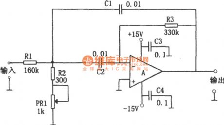
The single-peak filter composed of one operational amplifier is shown in the figure. This circuit only uses one operational amplifier and a few components to build up filter circuit that has the same performance composed of LC components. The resonant frequency can be easily tuned without changing the circuit gain. This circuit uses potentiometer PR1 to tune the resonant frequency. When the value of PR1 varies from minimum to maximum, the resonant frequency tuned range is 1580Hz, and the circuit gain hardly changes. (View)
View full Circuit Diagram | Comments | Reading(1305)
Overcurrent latch circuit composed of the M51958B
Published:2011/8/25 20:29:00 Author:TaoXi | Keyword: Overcurrent, latch circuit
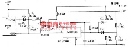
The overcurrent latch circuit is composed of the M51958B. Because the power supply is the multi-output power, if anyone of the channels is in the overcurrent protection state, the voltage will decrease, the optocoupler TLP521 cuts off, the side control PWM integrated circuit stops working, the power supply is protected. This circuit controls all of the PWM integrated circuits, and it has the overvoltage protection locking terminal. The R1-R5 are the dividing resistors, the set voltage of the midpoints is higher than the pin-2 peak voltage of the M51958B (10%-20%). The R1 and C2 decide the start time constant of the circuit, R6 is the dark current resistance of the TLP521 that can be used to prevent the optocoupler error action.
(View)
View full Circuit Diagram | Comments | Reading(1436)
The connector circuit with 3-line serial spot intelligent temperature sensor DS1620 and SP1 general line
Published:2011/8/13 2:37:00 Author:qqtang | Keyword: connector circuit, serial spot, temperature sensor
View full Circuit Diagram | Comments | Reading(744)
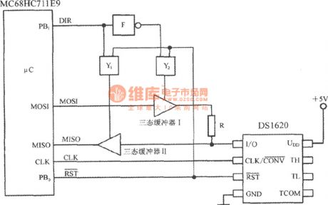
The micro heater temperature control circuit composed of 3-line connector intelligent temperature sensor DS1620
Published:2011/8/13 3:05:00 Author:qqtang | Keyword: micro heater, temperature control, temperature sensor
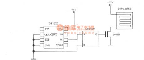
The micro heater temperature control circuit composed of 3-line serial spotconnector intelligent temperature sensor DS1620 is shown in the figure. (View)
View full Circuit Diagram | Comments | Reading(1668)
Pulse width modulation circuit composed of the μA741
Published:2011/8/25 22:31:00 Author:TaoXi | Keyword: Pulse width, modulation circuit
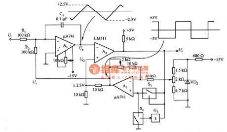
The pulse width modulation circuit composed of the μA741 is as shown in the figure. In this circuit, the A1 is the integral circuit, A2 is the comparator circuit; A3 is the reference voltage generating circuit. The operating principle: when the Ui=O, the Ur is the reference voltage, it is +/-5V. We suppose that the Ur=-5V, the comparation circuit of the inverting input port is UQ=-2.5V, the positive linearity of the integrator A1's output voltage Ua will increase. When the Ua is +2.5V, A2 outputs the reversal, S1 connects, the reference voltage Ur is +5V, the comparation voltage UQ is +2.5V. So A1 starts the backward integration process.
(View)
View full Circuit Diagram | Comments | Reading(1126)
Zero-cross driving circuit
Published:2011/8/26 1:37:00 Author:TaoXi | Keyword: Zero-cross, driving circuit
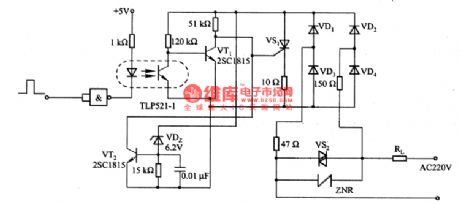
The zero-crossing driving circuit is as shown in the figure. The zero-crossing driver means the circuit can control the on/off of the current at the AC voltage zero-crossing point to reduce the switching surge amd the electromagnetic interference. In the circuit, the ZNR is the sensitive component which can be used to absorb the surge to protect the power components.
(View)
View full Circuit Diagram | Comments | Reading(964)
Electromagnetic valve driving circuit composed of the optical coupler
Published:2011/8/26 0:43:00 Author:TaoXi | Keyword: Electromagnetic valve, driving circuit, optical coupler
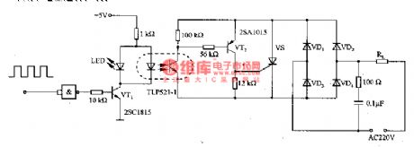
The electromagnetic valve driving circuit composed of the optical coupler is as shown in the figure. In this circuit, the TLP521-1 optical coupler isolates the input circuit and output circuit, the input circuit is the TTL level circuit, the output is the AC 220V electromagnetic valve, also the output can use the relay to control.
(View)
View full Circuit Diagram | Comments | Reading(1687)
Motorcycle color changing flashing taillight
Published:2011/8/26 3:27:00 Author:TaoXi | Keyword: Motorcycle, color changing, flashing taillight
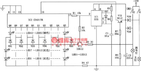
The Motorcycle color changing flashing taillight is as shown in the figure. The flashing taillight is composed of the red and green lights. In the normal driving, the red and green lights will turn on one by one. When the motorcycle is braking, all the green lights will turn off, all the red lights will trun on.
(View)
View full Circuit Diagram | Comments | Reading(712)
LM317 integrated voltage regulator circuit
Published:2011/8/29 3:36:00 Author:TaoXi | Keyword: integrated voltage, regulator circuit
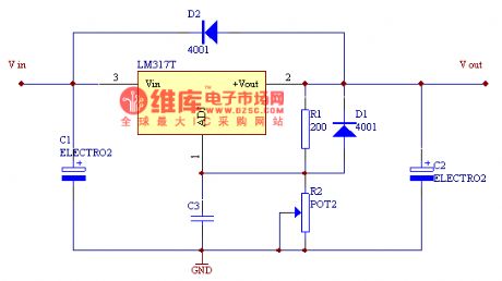
The LM317 is designed as the common adjustable integrated voltage regulator with the maximum output current of 2.2A, the output voltage range is 1.25-37V. The connection method is:
The reference voltage between pin-1 and pin-2 is 1.25V. In order to ensure the output voltage stabilizer performance, R1 is smaller than 240ohms. You can adjust the voltage regulator value by adjusting the value of R2. The D1 and D2 can be used to protect the LM317.
Uo=(1+R2/R1)*1.25
The LM317 integrated voltage regulator circuit (View)
View full Circuit Diagram | Comments | Reading(1590)
The clock synthesizer circuit composed of the MC74HC4046
Published:2011/8/29 3:41:00 Author:TaoXi | Keyword: clock synthesizer
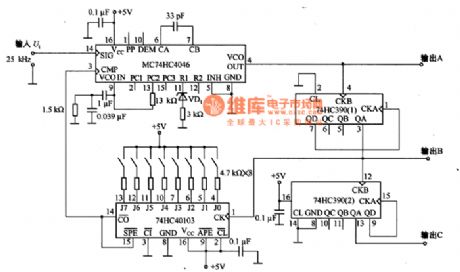
The clock synthesizer circuit which is composed of the MC74HC4046 is as shown in the figure, it can produce the 1MHZ~2OMHZ high precision clock signal. The output A is the 1MHZ~2OMHZ signal with the resolution ratio of 100kHz, the output B and output C outputs the signal with the 1/10 frequency respectively. If the input signal Vi is the 10kHz frequency demultiplication signal of the crystal circuit, the frequency precision of this circuit is the same as the crystal oscillator.
(View)
View full Circuit Diagram | Comments | Reading(3109)
The ultra-sonic liquid level indicating circuit composed of NE555
Published:2011/8/23 22:40:00 Author:qqtang | Keyword: ultra-sonic, liquid level, indicating circuit
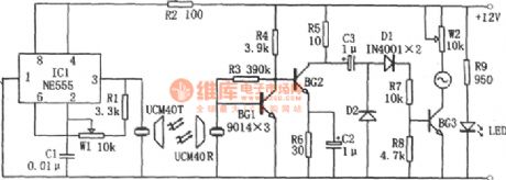
In the figure is the ultra-sonic liquid level indicating circuit. The circuit consists of the ultra-sonic emitting circuit and receiving circuit. The ultra-sonic emitting circuit consists of the 555, R1, W1, C1 and ultra-sonic emitting head UCM40T. The ultra-sonic receiving circuit consists of the receiving head UCM40R compatible with the emitting head, cascade amplifiers BG1 and BG2 and the test circuit. When the liquid level is approaching the receiving head, the voltmeter deflection angle is rising up, and the closer the liquid level is, the bigger the deflection angle will be. (View)
View full Circuit Diagram | Comments | Reading(714)
The analog thermistor composed of the current outputting precise integrated temperature sensor AD590
Published:2011/8/23 22:36:00 Author:qqtang | Keyword: analog thermistor, integrated temperature sensor

The simplest temperature test circuit composed of AD590 is shown in the figure. AD590 switches the temperature under test into current, which makes the microamp meter deflect. After the meter is marked, it can be used as the analog thermometer. To avoid the disturbance from the outside, the outgoing line should be the double stranded wire(stranded wire for short), and its length could be several hundred. (View)
View full Circuit Diagram | Comments | Reading(893)
The digital thermistor composed of the current outputting precise integrated temperature sensor AD590
Published:2011/8/23 22:36:00 Author:qqtang | Keyword: digital thermistor, temperature sensor
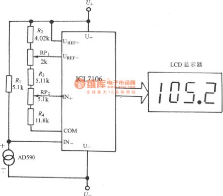
(View)
View full Circuit Diagram | Comments | Reading(2080)
The long-distance temperature test circuit composed of the intelligent temperature sensor TMP03
Published:2011/8/23 22:37:00 Author:qqtang | Keyword: temperature test circuit, intelligent temperature sensor
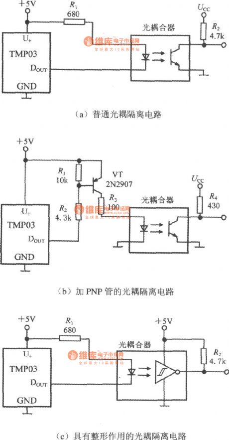
In the figure is the long-distance temperature test circuit composed of the intelligent temperature sensor TMP03. As there is a high common mode voltage on the transmission line, so the photo-coupler should be used to separate the output terminal. The circuits of the 3 photo-couplers are shown in figure (a), (b) and (c) respectively. (View)
View full Circuit Diagram | Comments | Reading(788)
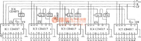
The random system output circuit composed of CD4017 (1)
Published:2011/8/12 10:43:00 Author:qqtang | Keyword: random system, output circuit
View full Circuit Diagram | Comments | Reading(1091)
TEA1046 Dual audio / voice transmission IC diagram
Published:2011/8/22 3:00:00 Author:Ecco | Keyword: Dual audio / voice transmission
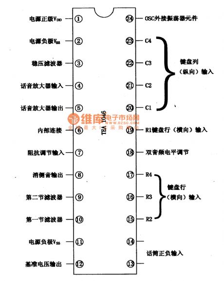
TEA1046 dual audio transmission integrated circuit is used in communication equipment for dual tone dialing and voice signal processing. 1. Features TEA1046 integrated circuit contains two-tone dialing signal generator, signal encoding and decoding circuit switching keyboard, voice amplifier, anti-side tone circuit, reference voltage regulator circuit, and other functional circuis. 2. pin function TEA1046 IC uses 24-pin dual in-line package, and the integrated circuit functions are shown in Figure 1-1.
(View)
View full Circuit Diagram | Comments | Reading(1084)
CXA1875AM-T4 I (2) C vice bus interface integrated circuit diagram
Published:2011/8/21 22:16:00 Author:Ecco | Keyword: vice bus, interface integrated circuit
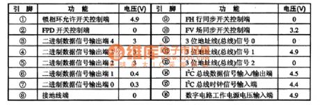
CXA1875AM-T4 is the I2C bus interface integrated circuit produced by Japanese Sony, and it is widely used in large-screen flat-panel or big screen picture in picture and other picture-large-screen color TV. 1. FeaturesCXA1875AM-T4 IC contains the binary data signal processing circuit, address bus circuit, IC Bus and other circuit. 2. pin functions and data CXA1875AM-T4 IC uses the DIP 16-pin package, and the integrated circuit pin functions and data are listed in Table 1.
(View)
View full Circuit Diagram | Comments | Reading(652)
Audio / video conversion integrated circuit diagram
Published:2011/8/21 22:21:00 Author:Ecco | Keyword: Audio / video conversion
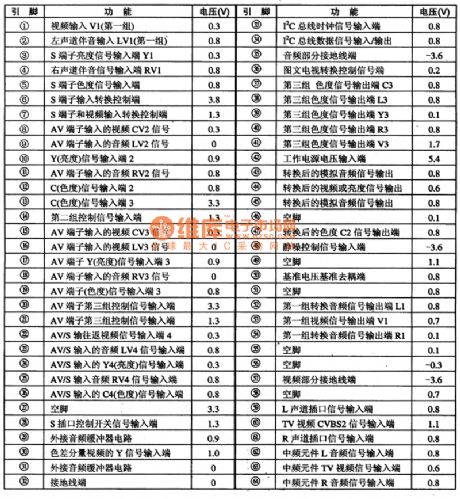
CXA2069Q is the new model audio / video conversion integrated circuit manufactured by Sony Corporation of Japan, and it is used in the Sony series of picture in picture, back projection color TV. 1. FeaturesCXA2069Q IC's input signal is high / medium frequency component output R / L channel TV audio signal, and the main screen of the video signal CVBSl, Vice-screen video signal CVBS2 and so on. CXA2069Q can also be input the four groups of signals to connect to the audio as Na R / L channel signal input end.2. Pin functions and data XA2069Q IC uses the 64-pin package, the integrated circuit pin functions and data are Table 1.
(View)
View full Circuit Diagram | Comments | Reading(793)
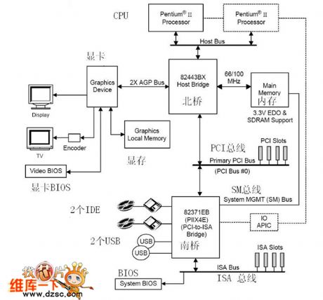
440bx board structure circuit diagram
Published:2011/8/24 1:57:00 Author:Ecco | Keyword: board structure
View full Circuit Diagram | Comments | Reading(726)
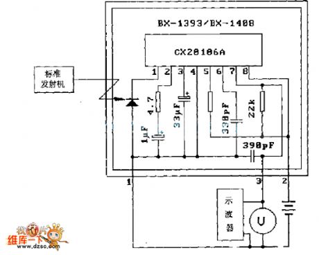
DX-1393/BX-1408 Typical application circuit diagram
Published:2011/8/25 1:30:00 Author:Ecco | Keyword: Typical application
View full Circuit Diagram | Comments | Reading(770)
| Pages:121/471 At 20121122123124125126127128129130131132133134135136137138139140Under 20 |
Circuit Categories
power supply circuit
Amplifier Circuit
Basic Circuit
LED and Light Circuit
Sensor Circuit
Signal Processing
Electrical Equipment Circuit
Control Circuit
Remote Control Circuit
A/D-D/A Converter Circuit
Audio Circuit
Measuring and Test Circuit
Communication Circuit
Computer-Related Circuit
555 Circuit
Automotive Circuit
Repairing Circuit