
Index 138
TRIAC_SUPPRESSES_RELAY_ARCING
Published:2009/7/14 23:02:00 Author:Jessie
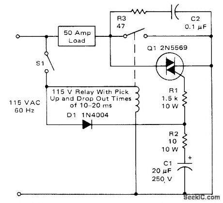
Circuit prevents arcing at contacts of relay for loads up to 50 A, by turning on as soon as it is fired by gate current; this occurs after S1 is closed but before relay contacts close. Once contacts are closed, load current passes through them rather than through triac. When S1 is opened, triac limits maximum voltage across relay contacts to about 1 V. Circuit permits use of smaller relay since it does not have to interrupt full load current.- Circuit Applications for the Triac, Motorola, Phoenix, AZ, 1971, AN-466, p 8. (View)
View full Circuit Diagram | Comments | Reading(1039)
±15_TO_±75_V_THRESHOLD
Published:2009/7/14 23:02:00 Author:Jessie
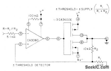
Precise timing and accurate threshold levels are assured by stable characteristics of input differential amplifier in CA 3080 variable opamp used to drive one of inverter/amplifier transistors in CA3600E array. For values shown, threshold voltage for given polarity is half of supply voltage used, in range of 3 to 15 V.- Circuit Ideas for RCA Linear ICs, RCA Solid State Division, Somerville, NJ, 1977, p 16. (View)
View full Circuit Diagram | Comments | Reading(660)
REGULATOR_OVERLOAD
Published:2009/7/14 23:00:00 Author:Jessie
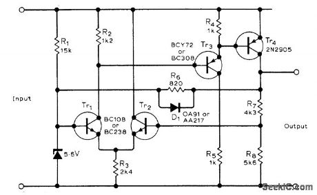
When output is shorted, germanium diode D1 turns on and draws current through R1, removing reference voltage across zener. Tr1 is then held off and turns Tr3 and Tr4 off to block load current. When short is removed, circuit recovers automatically.-D. E. Waddington Germanium Diode for Regulator Protection, Wireless World, March 1977, p 42. (View)
View full Circuit Diagram | Comments | Reading(1329)
DEMODULATOR_FOR_170_Hz_SHIFT
Published:2009/7/14 22:59:00 Author:Jessie

Converts RTTY audio tones of 2125 and 2295 Hz to DC pulses required for driving selector magnets of teleprinter. Coupling Iinks are added to standard 88-mH toroids as indicated.-I Schwartz, An RrrY Primer,CQ, Feb 1978,P 31-36. (View)
View full Circuit Diagram | Comments | Reading(628)
45_kHz_LOW_PASS_STATE_VARIABLE_FILTER
Published:2009/7/14 20:39:00 Author:May
Used In precision telephone-network active equalizer Camping value is 0.082, which requires 1% components. For high pass, take out-put from first opamp; for band pass, take output from second opamp.-D. Lancaster, Active-Filter Cookbook, Howard W Sams, Indianapolis, IN, 1975, p 147. (View)
View full Circuit Diagram | Comments | Reading(1701)
TAPE_MICROPHONE_PREAMP
Published:2009/7/14 22:54:00 Author:Jessie
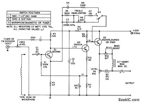
Uses silicon planer npn transistors, making it necessary to have temperature-compensating resistor in emitter circuit of first stage. Noiselevel is 66 db below reference level output with weighted measurement. Frequencyresponse is fiat within 0.25 db from 30 cps to 15 kc, and total harmonic distortionis 0.01% at 1.2 v output.- Transistor Manual, Seventh Edition, General ElectricCo., 1964, p 256. (View)
View full Circuit Diagram | Comments | Reading(904)
TTY_RESETS_CPU
Published:2009/7/14 22:54:00 Author:Jessie
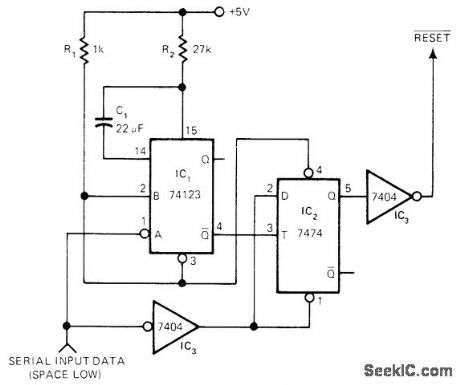
Circuit uses break key on TTY as reset button for microprocessor. Retrig-gerable mono IC1 monitors data input line from TTY, which goes low for spacing condition. During normal data input, constant spacing pulses in data retrigger mono, keeping IC2 reset. When break key is depressed, input data goes to steady space and IC1 times out. IC2 then transfers high on its data input to its output to produce reset signal for CPU. Values of R2 and C1 give 150-ms period for mono, suitable for baud rates of 110 and higher,-C. Sondgeroth, Reset Your CPU from Your TTY's Break Key, EDN Magazine, May 5, 1978, p 39. (View)
View full Circuit Diagram | Comments | Reading(804)
FREEZER_FAILUREALARM
Published:2009/7/14 22:54:00 Author:Jessie
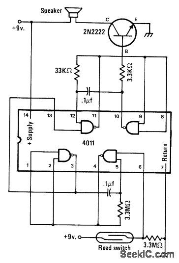
Loudspeaker is energized by 4011 audio oscillator and 2N2222 transistor operating from 9-V battery when ice melts and allows permanent magnet to drop on reed switch and close it. Magnet is bonded to wall inside of freezer with mixture of antifreeze and water.-J. A. Sandier, 11 Projects under $11, Modern Electronics, June 1978, p 54-58. (View)
View full Circuit Diagram | Comments | Reading(1118)
LOW_VOLTAGE_ALARM_1
Published:2009/7/14 22:53:00 Author:Jessie
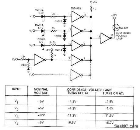
Simple indicator circuit uses hex inverter IC to monitor several different input voltages. Technique is flexible and easily modified for different voltage values (either positive or negative) and additional in-puts. When negative input (V1, V2, or V3) falls below breakdown voltage of its zener, logic 0 appears at inverter output (at wired-OR connection). Because lamp-driving inverter has logic 0 at its input, lamp goes out as no-go signal. When positive input V4 falls below predetermined value, logic 0 again causes no-go indication,-R. J. Buonocore, Under-Voltage Sensing Circuit, EDN/EEE Magazine, Dee. 1, 1971, p 48-49. (View)
View full Circuit Diagram | Comments | Reading(810)
15_25_kHz_SINE_WAVE
Published:2009/7/14 20:38:00 Author:May
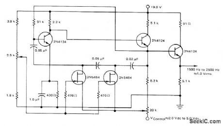
Three-section phase-shift oscillator is linear over its frequency range and has good sine waveform. Phase-shifting 2.5k network is included in feedback loop of amplifier to give voltage-controlled oscillator action.- Low Frequency Applications of Field-Effect Transistors, Motorola, Phoenix, AZ, 1976, AN-511A, p 8. (View)
View full Circuit Diagram | Comments | Reading(879)
52_MHz_WITH_VVC_FM
Published:2009/7/14 20:37:00 Author:May
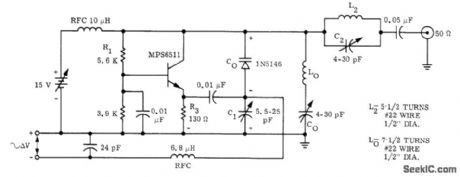

Voltage-variable capacitor CO rovides ±75 kHz modulation of basic 52-MHz transistor oscillator operating from 15-V supply. Modulation linearity is good for voltage inputs up to ±200 mV, making circuit suitable for commercial FM use.- FM Modulation Capabilities of Epicap VVC's, Motorola, Phoenix, AZ, 1973, AN-210, p 2. (View)
View full Circuit Diagram | Comments | Reading(752)
INSTANT_ULTIMATE_VALUE
Published:2009/7/14 22:51:00 Author:Jessie
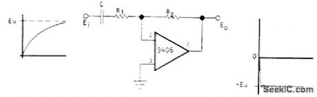
Circuit instantly computes ultimate value of logarithmically in-creasing input signal Ei y performing augmented differentiation that gives step function equal to ultimate value EU, Uses Optical Electronics 9406 opamp. Circuit values are computed from EU = EO = -R2EjR1 – R2Cdej/dt.- Derivative Circuit Indicates Ultimate Value Instantly, Optical Electronics, Tucson, AZ, Application Tip 10179.
(View)
View full Circuit Diagram | Comments | Reading(805)
AFSK_SHIFTS_UP_TO_20_kHz
Published:2009/7/14 22:50:00 Author:Jessie
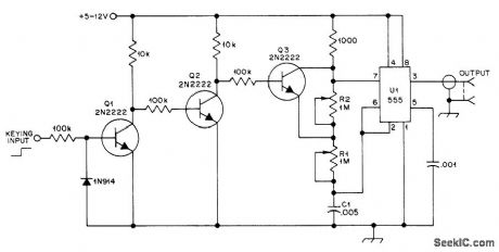
Wide-range generator can be tuned from 50 Hz to 20 kHz, for shifting between two frequencies as much as 20 kHz apart. UI is 555 timer connected as astable MVBR. When Q3 is biased off, charge/discharge currents for C1 flow chiefly through R1 and R2 to determine lower frequency of oscillation, When Q3 is on, R2 is effectively shorted and frequency is increased.Q1 acts as buffer and inverter so higher voltage at input gives higher tone. Keying occurs when input voltage exceeds 1 V with 5-V supply. If 10K supply resistor for al is reduced to 1000 ohms, keying voltage increases to 3V.-T. M. Whittaker, Wide-Range AFSK Generator, QST, May 1977, p 48. (View)
View full Circuit Diagram | Comments | Reading(1065)
FAST_SLEW_VCO_DRIVER
Published:2009/7/14 20:34:00 Author:May
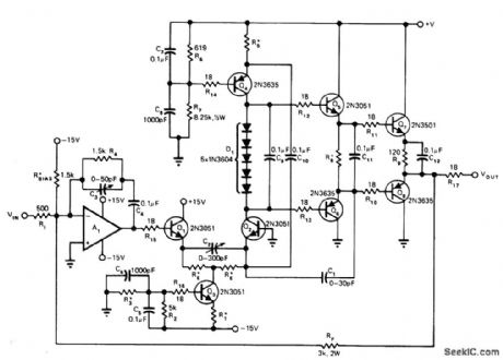
High-performance circuit slews at 4000 V/μs when operating from 80-V supply and provides output levels up to +30 VDC. Circuit handles large-signal modulation rates up to 20 MHz for 60-V varactors and small-signal bandwidths up to 86 MHz. Input opamp can be M. S. Kennedy Model 770 or other fast-input unit having -6 dB per octave rolloff. Operation in transimpedance configuration means associated buffer amplifier can have high gain. RE is 250 ohms, R1 is 100, R3 is 4.3K, R5 is 170, and R8 is 90.-H. Bunin, Low Cost VCO Driver Amplifiers Really Perform lf Designed Right, EDN Magazine, Oct. 5, 1974, p 51-55.
(View)
View full Circuit Diagram | Comments | Reading(971)
FSK_FOR_NRZ_INPUT
Published:2009/7/15 1:59:00 Author:Jessie
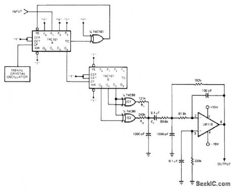
Crystal-controlled frequency-shift keyer accepts nonreturn-to-zero digital input and generates 5-V P-P FSK output signal having less than 3% total harmonic distortion, at standard 2.125- and 2.975-kHz radio-teletype frequencies. When input is low, counter A divides by seven; for high or logic 1 input, counter divides by five. Counter B divides by eight to produce required output frequencies. EXCLUSIVE-OR gates G1 and G2 generate fist approximation to desired sine-wave out-put, for filtering by three-pole active Butter-worth low-pass filter having 4.75-kHz cutoff.-K. Erickson, Frequency4hift Keyer Features Rock-Steady Operation, EDN Magazine, Jan. 5, 1977, p 44. (View)
View full Circuit Diagram | Comments | Reading(728)
BIPOLAR_PULSE_TRAINS
Published:2009/7/15 1:58:00 Author:Jessie
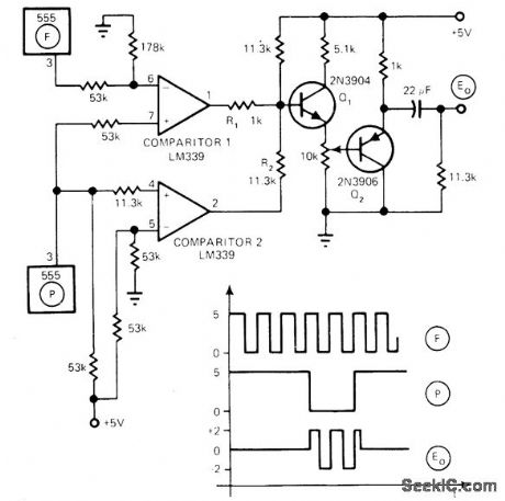
Output of Signeties 555 timer F, consisting of unipolar waveform varying from ground to +5 V, is converted to bipolar pulse train having duration equal to that of output pulse from lower 555 timer. While P is high, comparator 2 is on, forcing R2 to ground and placing base of Q1 at 2.5 V (because comparator 1 is off, forcing R1, high). Comparator 2 goes off when timer P goes low, and action of comparator 1 is turned on and off by timer F to produce bipolar pulse train at E0.-G. L. Assard, Derive Bipolar Pulses from a Unipolar Source, EDN Magazine, April 5, 1977, p 144. (View)
View full Circuit Diagram | Comments | Reading(1078)
AFSK_GENERATOR
Published:2009/7/15 1:58:00 Author:Jessie
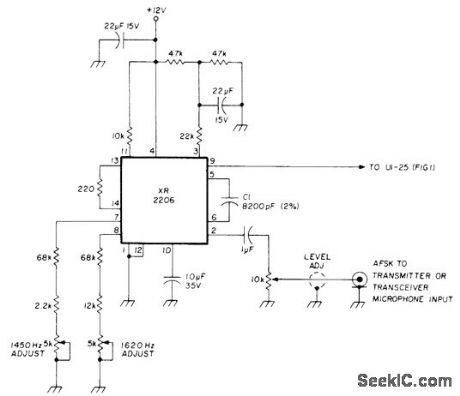
Uses phase-continuous frequency shift to prevent out-of-band transients while generating radio frequencies of 1450 and 1620 Hz. Second harmonic is outside passband of modern SSB equipment. Frequency of sine wave is determined by C1 and total resistance connected to pin 7 or 8 of Exar XR2206.-E. Kirchner, Serial Converter for 8-Level Teleprinters, Ham Radio, Aug. 1977, p 67-73. (View)
View full Circuit Diagram | Comments | Reading(927)
NONPRECISE_PHANTASTRON_VARIABLE_DELAY
Published:2009/7/15 1:58:00 Author:Jessie
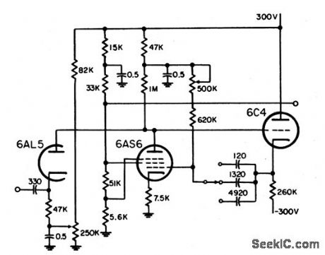
Used to delay beginning of crt sweep for expanded display. Provides three ranges: 0 to 5, 60, and 200 miles. Circuit is basically cathode-coupled phantastron, with additional coupling by returning suppressor and screen to same divider. Cathode follower reduces recovery time and provides low-impedance point for range switching.-NBS, Handbook Preferred Circuits Navy Aeronautical Electronic Equipment, Vol. 1, Electron Tube Circuits, 1963, p N9-3. (View)
View full Circuit Diagram | Comments | Reading(883)
GENERATOR_FOR_170_Hz_SHIFT
Published:2009/7/15 1:56:00 Author:Jessie
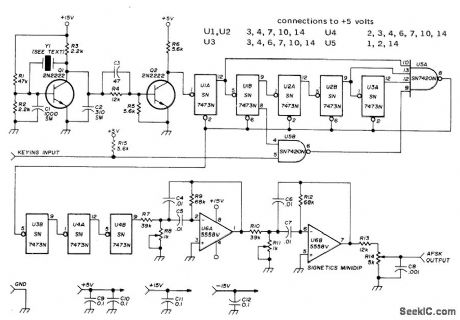
Provides precise 2125- and 2295-Hz audio tones without requiring counter to establish correct frequency, Used for adjusting AFSK oscillator, Crystal can be 459.259 kHz (channel 48), which with appropriate divider chains gives output frequencies accurate within 2 Hz while preserving 170-Hz relative shift within 0.1 Hz. For even greater ac-curacy, order crystal that has been adjusted to exactly 459.000 kHz. When input is grounded, divide ratio is 25 to give 2295 Hz. When input is high, divide ratio is 27 to give 2125 Hz. Pin 11 of U1-U4 and pin 7 of U5 are grounded.-H. Nurse, Crystal Controlled AFSK Generator, Ham Radio, Dec. 1973, p 14-17.
(View)
View full Circuit Diagram | Comments | Reading(1027)
LM322_ASTABLE
Published:2009/7/15 1:55:00 Author:Jessie
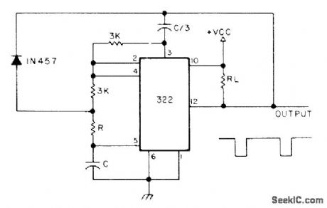
National LM322 timer generates narrow negative pulse whose width is approximately 2RC seconds. VCC is 4.5-20 V. Will drive loads up to 5mA. -H. M. Berlin, IC Timer Review, 73Magazine, Jan. 1978, p 40-45. (View)
View full Circuit Diagram | Comments | Reading(1243)
| Pages:138/471 At 20121122123124125126127128129130131132133134135136137138139140Under 20 |
Circuit Categories
power supply circuit
Amplifier Circuit
Basic Circuit
LED and Light Circuit
Sensor Circuit
Signal Processing
Electrical Equipment Circuit
Control Circuit
Remote Control Circuit
A/D-D/A Converter Circuit
Audio Circuit
Measuring and Test Circuit
Communication Circuit
Computer-Related Circuit
555 Circuit
Automotive Circuit
Repairing Circuit