
Index 126
High-precision long-range temperature measurement circuit composed of the ISO120 and XTR101
Published:2011/8/9 1:58:00 Author:Rebekka | Keyword: High-precision long-range temperature measurement
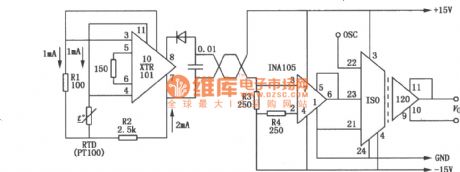
The high-precision long-range temperature measurement circuit composed of the ISO120 and XTR101 is mainly used in remote temperature measurement, temperature measurement accuracy is high and in the strong noise of the measurements. The ISO120 is the duty factor modulation / demodulation techniques designed a novel isolation amplifier. Isolation layerhas 2 matching lpF differential capacitors, the transmission is digital signal. The digital signal transmission will not affect the signal characteristics of isolated components of integrity. It also has good high frequency transient performance. The figure shows the high-precision long-range temperature measurement circuit composed of the ISO120 and XTR101. (View)
View full Circuit Diagram | Comments | Reading(719)
Op-amp relay delay release circuit diagram
Published:2011/8/17 2:30:00 Author:Rebekka | Keyword: Op-amp relay , delay release
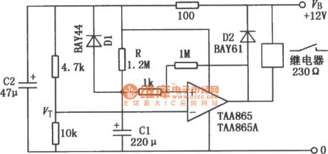
The figure shows the relay delay release circuit composed of operational amplifier circuit. When the power switch is turned on, the operational amplifier inverse input is added the voltage VTbetween the 4.7kΩ and 10 k Ω resistor, C1 has not charged, the same phase input is the low level. So operational amplifier output terminal is low level, the relays pulls in. At the same time, the power supply passes the 1.2 M Ω resistance and charge for the capacitor C1. Along with the increase of the capacitance C1, its charge voltage increases gradually. A period of time later the voltage will bein high level. (View)
View full Circuit Diagram | Comments | Reading(1571)
ULN3702Z/TDA2002A 12W audio power amplifier circuit diagram
Published:2011/8/17 2:24:00 Author:Rebekka | Keyword: 12W , audio power amplifier
ULN3702Z/TDA2002A are audio power amplifier integrated circuits,and theyuse the 5 feet into plastic packaging. The single inline radiator stents grounding potential, so no need to add insulation measures between the integrated circuits and the heat. According to the shape of the lead tube feet, it is divided into V type and the H two forms. The integrated circuit is ULX37012 / TDA2002 improvement products, the interior has high pressure protection circuit. The work power supply can be up to 26 V power supply voltage, if DC load rated current is 2.5 A, it uses appropriate heat sink, its power can be controlled to 60 W. (View)
View full Circuit Diagram | Comments | Reading(1029)
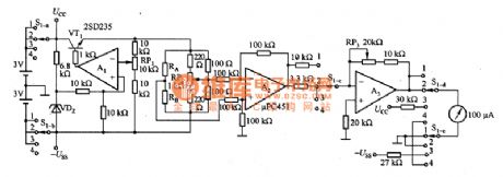
Q measurement incentive driver circuit diagram
Published:2011/8/17 3:03:00 Author:Rebekka | Keyword: Q measurement incentive driver

View full Circuit Diagram | Comments | Reading(543)
Narrow Pulse Driving Circuit
Published:2011/8/17 5:21:00 Author: | Keyword: Narrow, Pulse, Driving

The picture shows the circuit which could add enough reverse bias even for the narrow pulse. In the circuit shown in picture (a), when the VT1 is conducted, the current would be through R and VT3's base electrode. At the same time it would charge the capacitor C which is regarded as reverse bias power. If the VT1 is not conducted, the diode VD2 would make the VT2 conducted, the capacitor C's energy would be reversely added on the VD2's base electrode. If the carriers in VT2 are completely swept and over, it would reversely add the NSI's voltage on the VT3's base electrode through R2. For the circuit shown in picture (b), the reverse bias power C's voltage is also get from R2. The working principle is just the same with picture (a). (View)
View full Circuit Diagram | Comments | Reading(735)
Base Electrode Driving Circuit
Published:2011/8/13 7:52:00 Author:Robert | Keyword: Base Electrode, Driving
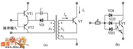
The base electrode driving circuit example is shown in the picture. When the base electrode current is big, to prevent the increasing of the storage time, it can use the Bekaa clamp circuit shown in picture (b). In the circuit, the base electrode current increases, when the transistor VT's saturation voltage is lower than UBE, the diode VD1 would be conducted. Thus it could prevent the increasing of the base electrode current. It is a circuit to prevent overexcitation.
The picture shows the base electrode driving circuit practical example.
(a)The drving circuit which the base electrode current is increasing as the ratio to the collector current.
(b)Bekaa clamp circuit. (View)
View full Circuit Diagram | Comments | Reading(784)
Production volume automatic counter circuit diagram 3
Published:2011/8/15 1:56:00 Author:Ecco | Keyword: Production volume, automatic counter
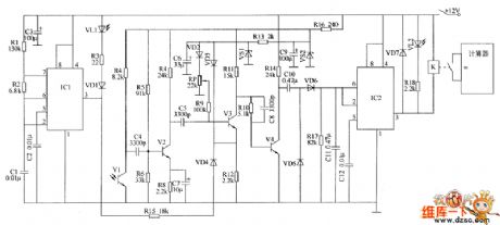
The production volume automatic counter circuit is composed of the infrared transmitter, infrared receiver processing circuit, voltage doubling rectifying circuit, control implementation circuit and counting display circuit, and it is shown as the chart. Infrared transmitter circuit consists of the infrared light-emitting diode VL1, resistors R1 ~ R3, diode VD1, capacitors C1 ~ C3 and time-base integrated circuit IC1. Infrared receiver processing circuit consists of the infrared phototransistor V1, transistors V2 ~ W, resistors M ~ R16, capacitors C4 ~ C9, regulator diodes VS1, VS2 and potentiometer RP. Voltage doubling rectifying circuit is composed of the capacitors CIO and C11, diode VD5 and resistors R17 and VD6.
(View)
View full Circuit Diagram | Comments | Reading(1024)
Welding power regulator circuit diagram
Published:2011/8/11 1:05:00 Author:Ecco | Keyword: Welding power regulator
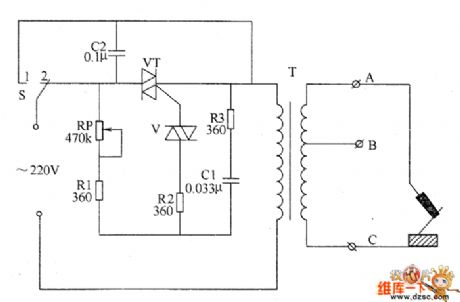
The welding power regulator circuit is composed of the control switch S, thyristor VT, two-way trigger diode V, potentiometer RP, resistors R1 ~ R3 and capacitors C1, C2, and it is shown as the chart. Adjusting the resistance of RP can change the charge rate of C1 to regulate the conduction angle of VT, then it can reach the purpose of adjusting the welding output power. R1 ~ R3 select the 1W metal film resistors. RP chooses the 2W organic solid potentiometer. C1 and C2 select th CBB capacitors with voltage in 630V. V uses the DB3 two-way trigger diode.
(View)
View full Circuit Diagram | Comments | Reading(4007)
TEA2161 switching power thick film IC diagram
Published:2011/8/15 21:36:00 Author:Ecco | Keyword: switching power, thick film IC
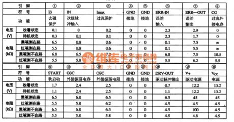
TEA2261 is the switching power thick film integrated circuit produced by Thomson, and it is widely used in Samsung series (such as C56226Z, C57230Z), Changhong CNS movement (eg, N2516, N2918), Feiyue FY703, Panda 2528,2928, C74P1, Venus C6418, etc. TV. TEA2261 IC's pin function and data are listed in Table 1-1.
(View)
View full Circuit Diagram | Comments | Reading(1043)
TEA2164 switching power thick film IC diagram
Published:2011/8/15 21:34:00 Author:Ecco | Keyword: switching power , thick film IC
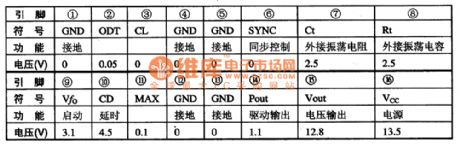
TEA2164 is the switching power thick film integrated circuit produced by Thomson, and it is widely used in Toshiba XH series (such as 2500XH, 2506XH, 2806XH), the West Lake series (such as C2918) of color television. 1. Features and functionsTEA2164 integrated circuit contains the oscillator circuit, starting circuit, driving pulse output circuit, delay circuit, synchronous control circuit, and other auxiliary functions circuit. 2. pin functions and data TEA2164 IC uses 16-pin double row package, and the pin function and data are listed in Table 1-1.
(View)
View full Circuit Diagram | Comments | Reading(784)
TEAl062 Calling integrated circuit diagram
Published:2011/8/15 21:30:00 Author:Ecco | Keyword: Calling integrated circuit
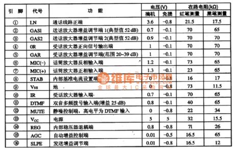
TEA1062 series of dedicated calling integrated circuits are widely used in telephone circuits. TEA1062 integrated circuit has the electrical chanting machine call and required line interface for dialing and call switching, and it is ideal for a wide range of calling integrated circuits. It uses 16-pin dual in-line package, and the integrated circuit pin functions and data are listed in Table 1-1.
(View)
View full Circuit Diagram | Comments | Reading(637)
M54543L loading motor driver IC diagram
Published:2011/8/14 22:17:00 Author:Ecco | Keyword: loading motor, driver IC
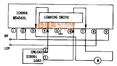
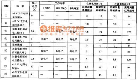
M54543L is the loading motor driver IC manufactured by Japan's Mitsubishi, and it is widely used in various camcorders. M54543L IC uses 9-pin single package, and the integrated circuit pin functions and data are listed in Table 1-1, the typical application circuit of manifold is shown in Figure 1.
(View)
View full Circuit Diagram | Comments | Reading(1121)
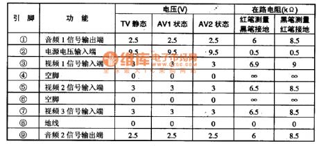
M52470AP audio- video switch IC diagram
Published:2011/8/14 22:13:00 Author:Ecco | Keyword: audio- video switching IC

M52470AP is the audio-video switching integrated circuit produced by Japanese Mitsubishi company, and it is widely used in TV Changhong CN-l5 movement and other brands of big screen color TV. M52470 IC contains 4-way inputs and 3-way switching electronic switch circuits. In the movements of CN-l5 color TV, the integrated circuit pin functions and data are listed in Table 1.
(View)
View full Circuit Diagram | Comments | Reading(1198)
M51327P electronic switch IC diagram
Published:2011/8/14 21:47:00 Author:Ecco | Keyword: electronic switch IC
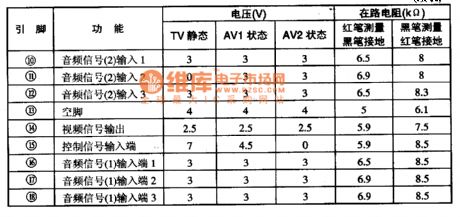
M51327P is the electronic switch integrated circuit produced by Japanese Mitsubishi company, and it is commonly used in video, audio and other systems used for signal switching. M51327P is used for TW / AV switch, and its integrated circuit pin functions and data are listed in Table 1.
(View)
View full Circuit Diagram | Comments | Reading(611)
The application circuit diagram of thermal conductivity gas sensor with RTD
Published:2011/8/14 22:01:00 Author:Ecco | Keyword: application circuit , thermal conductivity , gas sensor , RTD
The principle of the sensor: when it is in high temperature (200 to 800 ℃), the temperature of the sensor changes with the gas thermal conductivity, then the resistance of platinum resistor wire is detected. In the circuit, RA and RB are the platinum resistor wires, which are respectively used as detection device and temperature compensation element. Detection devices work according to temperature changes, so the bridge voltage requires a high stability. Compared to air, the hydrogen has larger thermal conductivity, which is easy to measure, therefore, the voltage stability of bridge is 0.1%.
(View)
View full Circuit Diagram | Comments | Reading(2260)
UC3842AN PWM IC diagram
Published:2011/8/11 1:15:00 Author:Ecco | Keyword: PWM IC
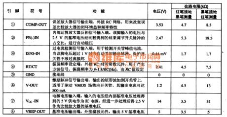
UC3842AN PWM pulse width modulation integrated circuit, which is widely used in DVD, VCD, SVCD DVD players, computers and display systems, and various other household appliances switching power supply circuits. 1. FeaturesUC3842AN integrated circuit contains the pulse signal generator, voltage regulator, pulse width adjustment circuit, voltage and current detection circuit. The internal manifold block diagram and typical application circuit are shown in Figure 1-1.
(View)
View full Circuit Diagram | Comments | Reading(7121)
Sound source selector
Published:2011/8/14 22:35:00 Author:Ecco | Keyword: Sound source selector
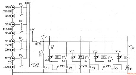
The sound source selector circuit is composed of the transistor V, diode VD, thyristors VTl-VW, control buttons Sl-S4, sound source indication LEDs VLl-VL4, relays Kl-K4, resistor Rl, audio input jacks XSI- XS8, and it is shown in Figure 3-203. Rl and R2 select the 1/4W or 1/8W carbon film resistors. Cl-C4 select the aluminum electrolytic capacitors with voltage in 16V. VD selects the lN4001 or 1N4007 silicon rectifier diode. VLl-VL4 use theφ3 or φ5mm light emitting diodes with different colors. V uses the S9014, C8050 or 3DGl2 silicon NPN transistors.
(View)
View full Circuit Diagram | Comments | Reading(5625)
Incandescent life extension device 1
Published:2011/8/10 3:52:00 Author:Ecco | Keyword: Incandescent, life extension device
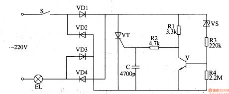
The incandescent life extension device circuit is composed of the rectifier diodes VDl-VD4, thyristor VT, resistors Rl-R4, capacitor C, voltage regulator diode VS and transistor V, and it is shown in Figure 3-197. Rl-R4 use 1/4W carbon film resistors or metal film resistors. C uses the high-frequency ceramic capacitor. VDl-VD4 select the 1N4007 silicon rectifier diodes. VS selects the 1/2W, 24V silicon zener diode. V uses C8050 or S8050, 3DGl2 other types of silicon NPN transistor. VT uses MCRlO0-6 or MCRlO0-8, BTl69D thyristor.
(View)
View full Circuit Diagram | Comments | Reading(689)
Incandescent life extension device 2
Published:2011/8/10 3:55:00 Author:Ecco | Keyword: Incandescent, life extension device
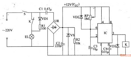
The incandescent life extension device circuit is composed of the filament preheating circuit, power supply circuit and delay control circuit, and it is shown in Figure 3-198. Filament preheating circuit consists of diode VDl, current limiting resistor Rl and incandescent EL. Power supply circuit is composed of the light switch, step-down circuit capacitor Cl, bridge rectifier UR, filter capacitor C2, resistor R2 and discharge regulator diode VS. Rl and R2 select the 1/2W metal film resistors. RP uses the small solid potentiometer or variable resistor. VDl selects the 1N4007 silicon rectifier diode; VD2 and VD3 choose the 1N4148 silicon switch diodes.
(View)
View full Circuit Diagram | Comments | Reading(642)
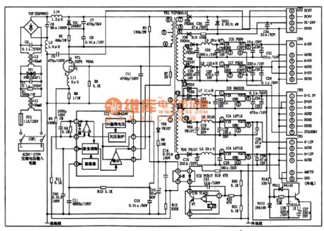
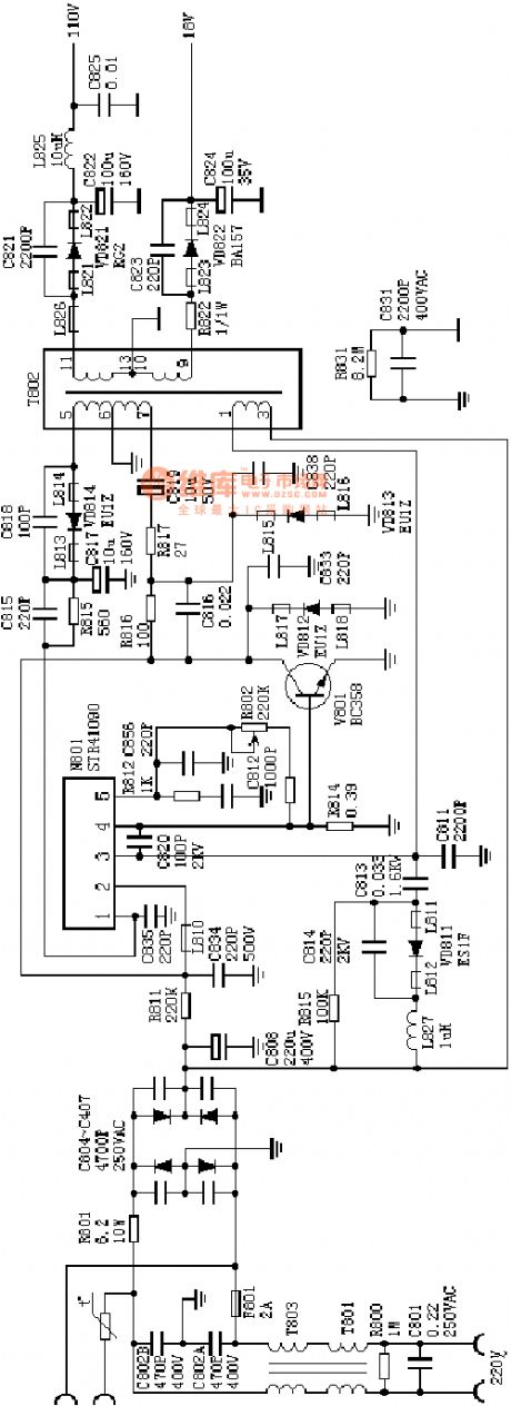
the absolutely useful switch power supply:the STR41090 power supply(A4)
Published:2011/8/13 6:46:00 Author:Ariel Wang | Keyword: absolutely useful , switch power supply
View full Circuit Diagram | Comments | Reading(859)
| Pages:126/471 At 20121122123124125126127128129130131132133134135136137138139140Under 20 |
Circuit Categories
power supply circuit
Amplifier Circuit
Basic Circuit
LED and Light Circuit
Sensor Circuit
Signal Processing
Electrical Equipment Circuit
Control Circuit
Remote Control Circuit
A/D-D/A Converter Circuit
Audio Circuit
Measuring and Test Circuit
Communication Circuit
Computer-Related Circuit
555 Circuit
Automotive Circuit
Repairing Circuit