
Index 132
RGB_TO_NTSC_CONVERTER
Published:2009/7/14 21:54:00 Author:Jessie
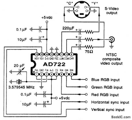
This figure shows an RGB-to-NTSC converter circuit. Note that the input sweep rates, interlace, overscan, and program content must be TV-compatible if you want useful results. The AD722 is manufactured by Analog Devices. (View)
View full Circuit Diagram | Comments | Reading(5029)
LOGAMP_ZERO_CROSSING_DETECTOR
Published:2009/7/14 21:54:00 Author:Jessie
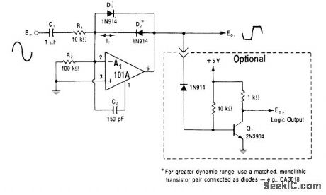

Feedback current for A1 creates logarithmic output voltage due to diodes D1 and D2. A1 is connected in feedforward mode to optimize speed and minimize phase error at high frequencies. 0utput voltage is nominally ±Vf, where Vf is forward voltage drop of either diode. Dynamic range of circuit is about 70 dB. If higher or constant output voltages are required, add optional connection of saturated switch that delivers 0-5 V output.-W. G. Jung, IC Op-Amp Cookbook, Howard W Sams, Indianapolis, IN, 1974, p229-230. (View)
View full Circuit Diagram | Comments | Reading(789)
PULSE_FREQUENCY_DIVIDER
Published:2009/7/14 21:40:00 Author:May
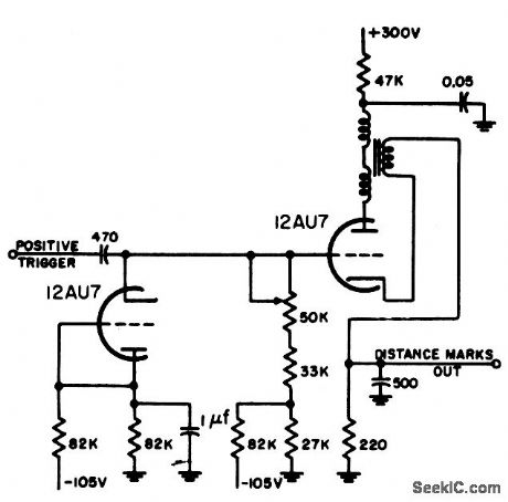
Plate-to-cathode coupled blocking oscillator is used to divide from high to low pulse frequency, as required in radar distance-mark generator. Circuit is highly stable with respect to heater voltage variations.-NBS, Handbook Preferred Circuits Navy Aeronautical Electronic Equipment, Vol. 1, Electron Tube Circuits, 1963, p N7-1. (View)
View full Circuit Diagram | Comments | Reading(786)
FSK_GENERATOR
Published:2009/7/14 22:10:00 Author:Jessie
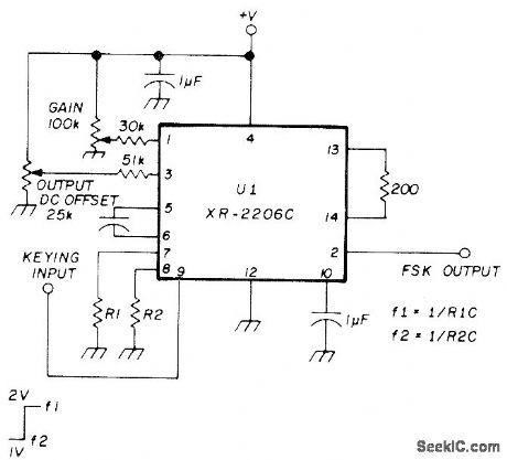
Simple frequency-shift keyer uses Exar XR-2206C IC. Keying input is applied to pin 9. Mark frequency f1 is 1/R1C and space frequency f2 is 1/R2C, with C connected between pins 5 and 6.-E. Noll, VHF/UHF Single-Frequency Conversion, Ham Radio, April 1975, p 62-67. (View)
View full Circuit Diagram | Comments | Reading(1447)
PCM_FREQUENCY_REFERENCE
Published:2009/7/14 21:39:00 Author:May
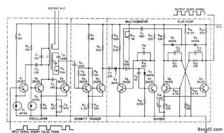
Coherently switched oscillator, 90° phase shifter, Schmitt trigger, and frequency-dividing multivibrator and flip-flop together derive constant-frequency square-wave output clock signal from frequency-shifted subcarrier oscillator of f-m/f-m telemetry system.-R. C. Onstad, New Coherent Keyer Simplifies Pulse-Code Telemetry, Electronics, 35:26, p 71-73. (View)
View full Circuit Diagram | Comments | Reading(686)
ZERO_DETECTOR_WITH_HYSTERESIS
Published:2009/7/14 21:38:00 Author:May
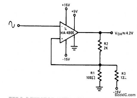
ZERO DETECTOR WITH HYSTERESIS-Circuit using one section of Harris HA-4900/4905 precision quad comparator as Schmitt trigger has 100-mV hysteresis. Suitable for applications requiring fast transition times at output even though input signal approaches zero crossing slowly. Hysteresis loop also reduces false triggering by input noise. Output jumps to 4.2 V at instant when input reaches -100 mV after dropping to 0 V. Output drops from 4.2V to 0 V when input passes through 0 V in positive direction and reaches +100 mV.- Linear & Data Acquisition Products, Harris Semiconductor, Melbourne, FL, Vol. 1, 1977, p 2-96.
(View)
View full Circuit Diagram | Comments | Reading(1421)
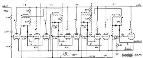
CASCADED_DISTANCE_MARK_DIVIDER
Published:2009/7/14 21:38:00 Author:May
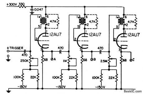
With 1-mile markers used as input trigger, output A, B, and C give 2 to 5,10 to 25, and 20 to 50-mile distance marks, respectively, Grid Potenliometers control exact mile mark obtained at each output,-NBS, Handbook Preferred Circuits Navy Aeronautical Electronic Equipment. Vol.1, Electron Tube Circuits,1963, p N7-5. (View)
View full Circuit Diagram | Comments | Reading(612)
ELECTRONIC_LOCK
Published:2009/7/14 22:06:00 Author:Jessie
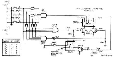
Correct combination of switches S1-S5 must be actuated to energize relay in series with ignition switch of auto or any other type of electric lock. If wrong combination is used, lock cannot be opened until resetting combination is entered,When car ignition is turned off, ignition relay should be reset (contact opened) by pressing S6.With connections shown, switches S2,S4,andS5 must be depressed simultaneously to oρen (set) lock. If error is made, output of fault gate goes to logic 1 and contacts of relay 2 will open, After error, S1 and S3 must be depressed simultaneously to reset lock before opening combination can be used again. Switches can be connected for any other desired combinations.-L. F. Caso, Electronic Combination Lock Offers Double Protection, Electronic, June 27, 1974, ρ 110; reprinted in ″Circuits for Electronics Engineers,″Electronics,1977, p 346. (View)
View full Circuit Diagram | Comments | Reading(1860)
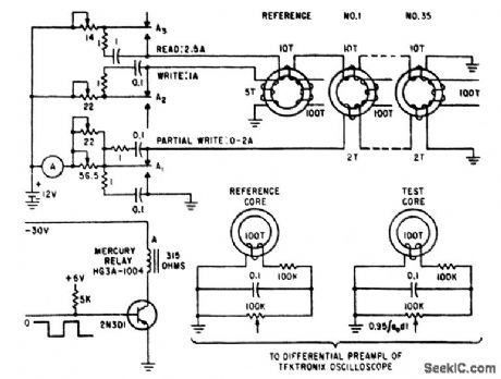
DIGITAL_MAGNETIC_CORE_DIVIDER
Published:2009/7/14 21:37:00 Author:May
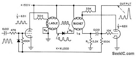
Frequency-divider chain uses pairs of rectangular hysteresis-loop magnetic cores as counting elements. Has high accuracy and stability. First core (ladle) is driven to saturation by each input pulse. Constant-voltage integral output from ladle core drives second bucket core. With appropriate turns ratios of windings, bucket core can be made to walk up its hysteresis loop in any number of predetermined steps. Successful single-stage dividers have been made up to scales of 17, with reliable operation from 10 to 50 kc.-A. Rose, Magnetic-Core Divider for ITV Sync Generators, Electronics, 31:15, p 76-77. (View)
View full Circuit Diagram | Comments | Reading(927)
DUAL_DELAY
Published:2009/7/14 21:37:00 Author:May
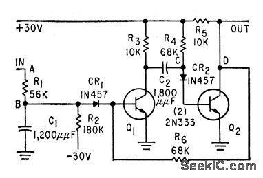
Two-transistor circuit produces pulses of finite width that start finite lime after reference pulse. Initial delay is determined by R1-R2-C1 and pulse width by C2-R4.-H. P. Brockman, Circuit Provides Dual Delay, Electronics, 32:18, p 62-65. (View)
View full Circuit Diagram | Comments | Reading(751)
3_kHz_TONE_LOCK
Published:2009/7/14 22:00:00 Author:Jessie
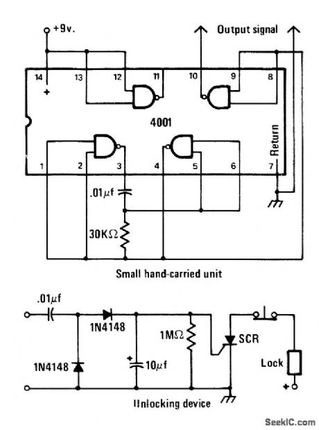
Electric door lock opens only when signal voltage of about 3 kHz is applied to two exposed terminals by holding compact single-IC AF oscillator against terminals. Will not respond to DC or 60-Hz AC. Pocket oscillator operates from 9-V transistor radio battery, with current drawn only when output prongs are held against lock terminals,SCR can be any type capable of handling current drawn by electric lock. -J. A. Sandler, 11 Projects under $11, Modern Electronics, June 1978, p 54-58. (View)
View full Circuit Diagram | Comments | Reading(790)
LINE_OPERATED_DELAY
Published:2009/7/14 22:23:00 Author:Jessie
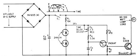
Operates directly from 117V a-c line to provide time delays adjustable from 8 millisec to 5 sec for lamp loads up to 100 w.-D. V. Jones, Quick-0n-The-Trigger Design. Electronics.38:12,p105-110. (View)
View full Circuit Diagram | Comments | Reading(727)
VARIABLE_DELAY_FOR_ANALOG_SIMULATION
Published:2009/7/14 22:21:00 Author:Jessie

Uses thick-walled ferrite cores to store voltage levels as flux levels.-W. C. Till and W. H. Ko. Versatile Analog storage uses ferrite Cores. Electronics.35 39,P60-63 (View)
View full Circuit Diagram | Comments | Reading(636)
TAPE_AS_RTTY_BUFFER
Published:2009/7/14 22:27:00 Author:Jessie
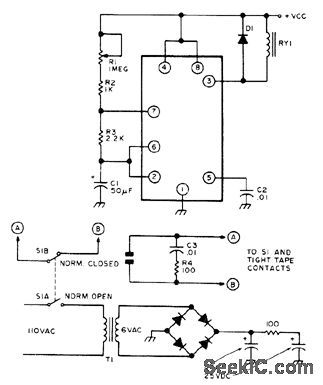
Developed to give constant-speed amateur radioteletype transmissions despite erratic keyboarding speeds Uses NE555 timer chip as free-running MVBR whose speed can be varied by R1 down to about 1 character every 15 s or up to full machine speed. Can be used with any automatic send-receive machine. Keep enough slack in punched paper tape to permit backspacing and correcting errors before they are sent. With 5-V supply shown, 6-V SPST DC relay can be used.-B. Gulledge, Mechanical RITY Buffer, 73 Magazine.Oct.1976, p 74. (View)
View full Circuit Diagram | Comments | Reading(685)
FOLDBACK_CURRENT_LIMITER
Published:2009/7/14 22:26:00 Author:Jessie
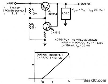
Provides overload and short-circuit protection for load while isolating malfunctioning circuit from other loads on common supply bus. In normal operation, Q1 is saturated. When load attempts to draw more than this saturation value, base current of Q1 cannot maintain saturation so voltage across unmarked resistor drops and current through Q1 drops correspondingly. When load is shorted, Q2 goes off and short-circuit current folds back to safe lower value. Choose value of unmarked resistor to ensure saturation of Q1 at load current. -S. T. Venkataramanan, Simple Circuit Isolates Defective Loads, EDN Magazine, Jan. 20, 1978, p 114. (View)
View full Circuit Diagram | Comments | Reading(4629)
MEASURING_NEARLY_SIMULTANEOUS_EVENTS
Published:2009/7/14 22:30:00 Author:Jessie
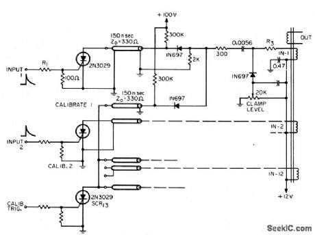
Used for measuring 12 events that can be as close together 20 nsec and as far apart as 200 nsec. Twelve identical circuits, one for each trigger, drive magnetostrictive delay line for serializing events.-R. P. Rufre, How to Measure Simultaneous Events with Magnetostrictive Delay Lines, EEE, 14:5, p44-49. (View)
View full Circuit Diagram | Comments | Reading(774)
VCO_FOR_FREQUENCY_SYNTHESIZER
Published:2009/7/14 21:37:00 Author:May
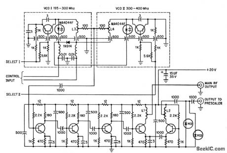
Digital synthesizer uses two vco's to covel 190 to 400 Mc, giving choice of 3,500 channels for transceiver in military uhf band without tuning. Output to prescaler is limited with hotcarrier diodes. Control voltage acts on diffused-junction varactors.-L. F. Blachowicz, Dial any Channel,500 Mhz,Electronics,39:9,p 60-69. (View)
View full Circuit Diagram | Comments | Reading(979)
SILICON_CONTROLLED_SWITCHES_DIVIDE_FRE_QUENCY_BY_100
Published:2009/7/14 21:35:00 Author:May
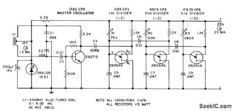
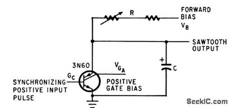
Each 3N60 stage divides input frequency by 10 while serving as relaxation oscillator, for frequencies from 250 kc down to fraction of cycle. Circuit can also be used as sawtooth generator.-R. J. Wold, 4-lerminal Controlled Switch Divides Frequencies by 10, Electronics, 37:18, p 81-82. (View)
View full Circuit Diagram | Comments | Reading(742)
SYNC_STRIPPER
Published:2009/7/14 21:35:00 Author:May
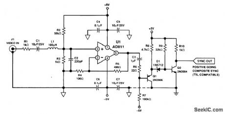
This circuit provides a sync-stripping function. The output is positive-going TTL-compatible. (View)
View full Circuit Diagram | Comments | Reading(1038)
ITV_DIVIDER_CHAIN
Published:2009/7/14 21:35:00 Author:May
Magnetic-core frequency divider counts 31.5-kc input signal down by 525 to produce 40.v 10-microsec output at 60 pps. Bias windings are series-connected in pairs to simplify circuit. Gives high accuracy and stability.-A. Rose, Magnetic-Core Divider for ITV Sync Generators, Electronics, 31:15, p 76-77. (View)
View full Circuit Diagram | Comments | Reading(744)
| Pages:132/471 At 20121122123124125126127128129130131132133134135136137138139140Under 20 |
Circuit Categories
power supply circuit
Amplifier Circuit
Basic Circuit
LED and Light Circuit
Sensor Circuit
Signal Processing
Electrical Equipment Circuit
Control Circuit
Remote Control Circuit
A/D-D/A Converter Circuit
Audio Circuit
Measuring and Test Circuit
Communication Circuit
Computer-Related Circuit
555 Circuit
Automotive Circuit
Repairing Circuit