
Index 124
Mazda central control unit circuit diagram
Published:2011/8/24 1:48:00 Author:Ecco | Keyword: Mazda , central control unit

View full Circuit Diagram | Comments | Reading(871)
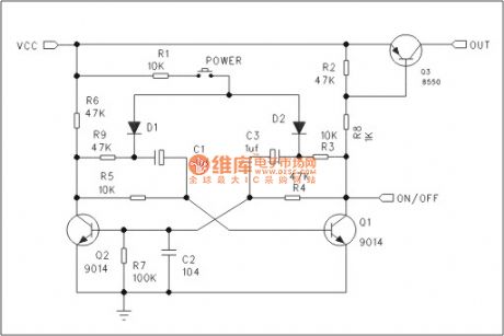
Bistable unilateral touching switch circuit
Published:2011/8/23 2:10:00 Author:Ecco | Keyword: Bistable , unilateral touching switch
View full Circuit Diagram | Comments | Reading(763)
Bistable circuit
Published:2011/8/23 2:10:00 Author:Ecco | Keyword: Bistable circuit
View full Circuit Diagram | Comments | Reading(826)
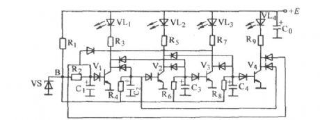
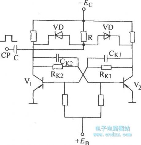
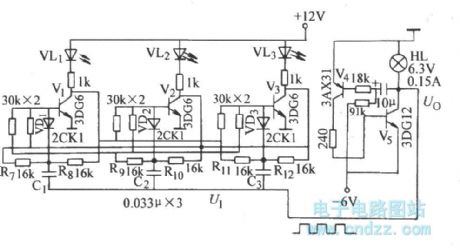
Four-tube astable circuit
Published:2011/8/23 2:17:00 Author:Ecco | Keyword: Four-tube astable circuit
View full Circuit Diagram | Comments | Reading(683)
Bistable counting base trigger circuit
Published:2011/8/23 2:17:00 Author:Ecco | Keyword: Bistable counting , base trigger circuit
View full Circuit Diagram | Comments | Reading(693)
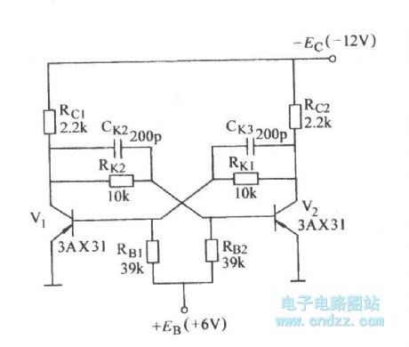
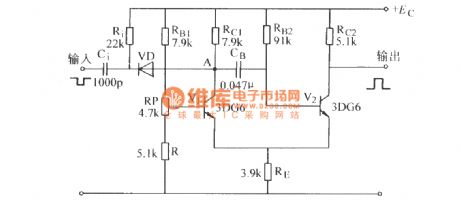
Bistable counting collector trigger circuit
Published:2011/8/23 2:13:00 Author:Ecco | Keyword: Bistable counting , collector trigger circuit
View full Circuit Diagram | Comments | Reading(655)
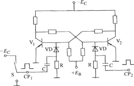
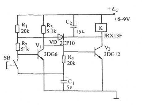
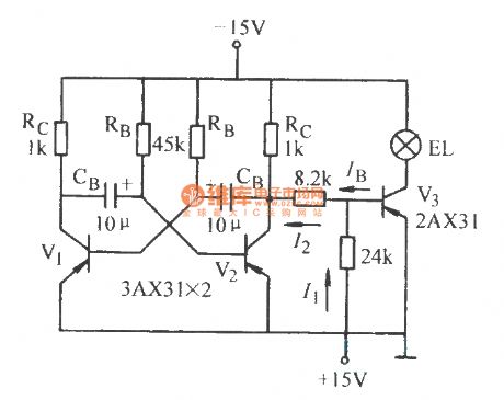
Bistable touching switch circuit
Published:2011/8/23 2:09:00 Author:Ecco | Keyword: Bistable touching switch
View full Circuit Diagram | Comments | Reading(900)
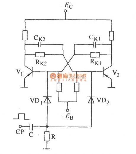
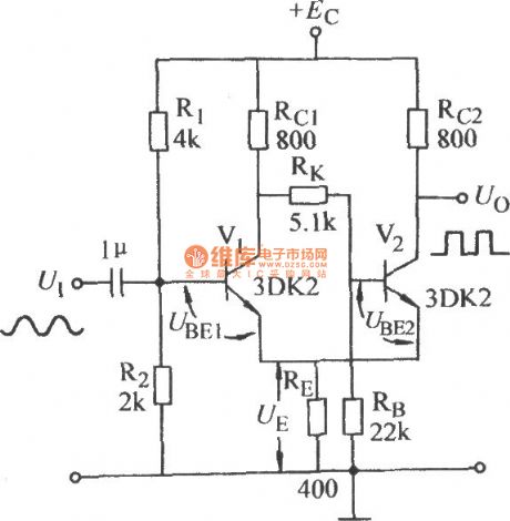
Emitter coupled bistable circuit
Published:2011/8/23 2:21:00 Author:Ecco | Keyword: Emitter coupled bistable
View full Circuit Diagram | Comments | Reading(737)
Emitter coupled monostable circuit
Published:2011/8/23 2:22:00 Author:Ecco | Keyword: Emitter coupled monostable
View full Circuit Diagram | Comments | Reading(767)
Three steady-state circuit
Published:2011/8/23 2:05:00 Author:Ecco | Keyword: Three steady-state circuit
View full Circuit Diagram | Comments | Reading(656)
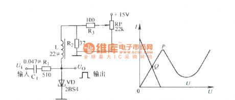
Tunnel diode bistable circuit
Published:2011/8/23 2:04:00 Author:Ecco | Keyword: Tunnel diode bistable
View full Circuit Diagram | Comments | Reading(1238)
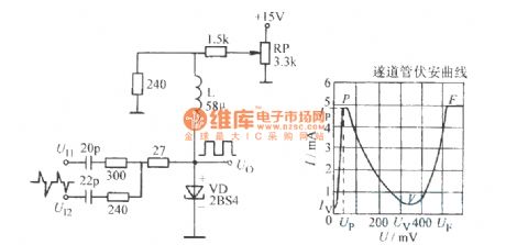
Tunnel diode astable circuit
Published:2011/8/23 2:04:00 Author:Ecco | Keyword: Tunnel diode astable
View full Circuit Diagram | Comments | Reading(1087)
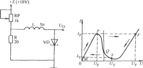
Tunnel diode monostable circuit
Published:2011/8/23 2:03:00 Author:Ecco | Keyword: Tunnel diode monostable
View full Circuit Diagram | Comments | Reading(1180)
Astable flashing circuit
Published:2011/8/23 2:07:00 Author:Ecco | Keyword: Astable flashing circuit
View full Circuit Diagram | Comments | Reading(701)
Stable single-button electronic switching circuit
Published:2011/8/23 2:24:00 Author:Ecco | Keyword: Stable single-button , electronic switching circuit
View full Circuit Diagram | Comments | Reading(709)
Mouse circuit diagram
Published:2011/8/23 2:02:00 Author:Ecco | Keyword: Mouse
View full Circuit Diagram | Comments | Reading(4212)
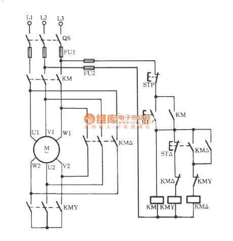
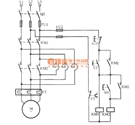
Manual contactor Y-△ buck starting circuit
Published:2011/8/23 1:59:00 Author:Ecco | Keyword: Manual contactor , Y-△ buck starting
View full Circuit Diagram | Comments | Reading(750)
Manually series reactance starting three-phase motor circuit
Published:2011/8/23 2:01:00 Author:Ecco | Keyword: Manually series, reactance starting , three-phase motor
View full Circuit Diagram | Comments | Reading(858)
MAX1582/MAX1582Y white LED driver circuit diagram
Published:2011/8/11 3:35:00 Author:Lucas | Keyword: white LED driver

MAX1582/MAX1582Y are the boost converter white LED drivers with dual output and high efficiency, and they are widely used to drive the primary and secondary screen white LED backlight display in mobile phones, and the power consumption is reduced by 25%. MAX1582/MAX1582Y can drive six series of white LEDs by constant current, thus they can provide dual display (primary and second) backlight driver for mobile phones and other portable electronic devices, and they do not need to configure the current limiting resistors. Its proprietary dual-output, step-up pulse-width modulation (PWM) converter is built-in 30V, low RDS-ON, N-channel MOSFET switch, which can improve efficiency and extend battery life.
(View)
View full Circuit Diagram | Comments | Reading(612)
XC9103 white LED driver circuit diagram
Published:2011/8/11 3:27:00 Author:Lucas | Keyword: white LED driver
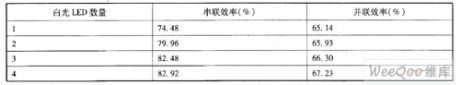
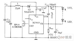
Figure 1 is the commonly series white LED driver circuit schematic, and the driver IC in the figure is the XC9103 Series DC / DC converter. When it uses XC9103 Series devices, it can use the ceramic capacitor as the output capacitor CL to suppress unwanted signal radiation. In Figure 1, the step-up DC / DC converter outputs white LED drive current, of which value is equal to the value from FB pin control voltage dividing the resistance of the connecting resistor. XC9103's FB-pin control voltage is 0.9V, XC6367's FB-pin control voltage is 1.0V. Therefore, changing the resistance can adjust white LED drive current to the desired value.
(View)
View full Circuit Diagram | Comments | Reading(842)
| Pages:124/471 At 20121122123124125126127128129130131132133134135136137138139140Under 20 |
Circuit Categories
power supply circuit
Amplifier Circuit
Basic Circuit
LED and Light Circuit
Sensor Circuit
Signal Processing
Electrical Equipment Circuit
Control Circuit
Remote Control Circuit
A/D-D/A Converter Circuit
Audio Circuit
Measuring and Test Circuit
Communication Circuit
Computer-Related Circuit
555 Circuit
Automotive Circuit
Repairing Circuit