
Index 120
Maintenance Circuit of Beijing Cherokee BJ2021 Light Off-road Vehicle AC Generator
Published:2011/8/14 7:37:00 Author:Michel | Keyword: Cherokee, Light Off-road Vehicle, AC Generator, Maintenance Circuit
AC Generator Maintance
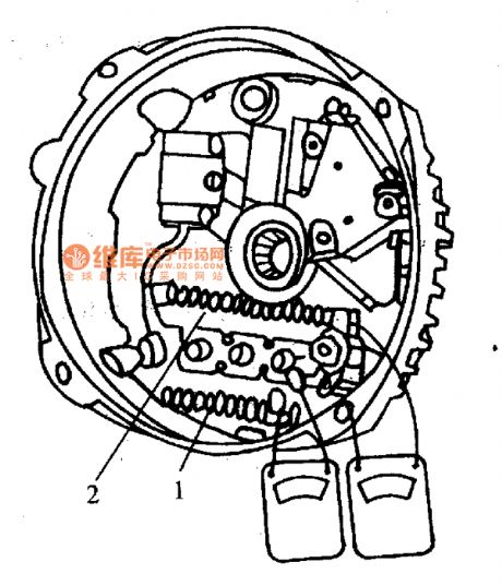
Beijing Cherokee uses ko-remy company ac generators, the output current is 56A, maximum output current is 61A.It uses V type more pulley groove.First, rotor.Its structure is similar to domestic ac generator rotor winding resistance and magnetic field is 2.2-3.0 ℃ Ω (When it is 27℃). Second,Stator. Three-phase stator winding is connected in triangular.Third,bridge rectifiers. As a separate parts,it is composed of six diodes.And if one diode is damaged, the rectifier assembly should be replaced.Inspection of the rectifier is shown as figure 1.The multimeter electric block is used to record the resistance value.The two touch needles touch one of the insulation heat sheet 2 and three winding.The other two winding should have the same result according to the above steps, or the diodes are damaged.
(View)
View full Circuit Diagram | Comments | Reading(1055)
High Efficiency Charger Circuit of SI8050S
Published:2011/7/23 6:08:00 Author:Michel | Keyword: High Efficiency, Charger Circuit
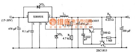
The above picture is high efficiency charger circuit of SI8050S.There are switch transistor and control circuit within SI8050S.Dividing resistor R1 and R2 are used for setting output voltage and the circuit voltage is 13.72V.Rs is used to test output current and SI8050S output voltage are regulated by VT1 and VT2.Thus it is consistent with voltage of charging batteries and it outputs about 3A constnt current.In this circuit,the input voltage Ui is +17~+30V and the maximum output voltage U。is 13.8V and the current is 3A.Rs resistance value is confirmed according to the following formula,namely,Rs=UBE/3A=0.7V/3A≈0.23Ω and 0.22Ω is chosen in the circuit. (View)
View full Circuit Diagram | Comments | Reading(2101)
Beijing Cherokee BJ2021 Light Off-road Vehicle Starter Parameter Circuit
Published:2011/8/14 8:22:00 Author:Michel | Keyword: Cherokee, Off-road Vehicle, Starter Parameter Circuit
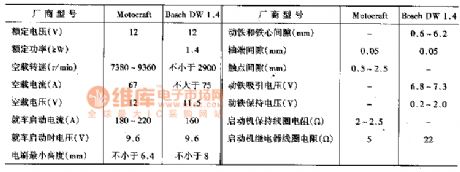
It uses DW1·4 electromagnetic control type and permanent magnet decelerating starter produced by Germany Bosch company.It uses three permanent magnets to replace the magnetic field winding and the core.It adds one level planetary gear reducer,which greatly reduces the volume and quality of starter.The starter's relative parameter are shown as table 1.
Tabke 1:Starter Parameter (View)
View full Circuit Diagram | Comments | Reading(714)
Parallel Connection Regulating Circuit of TL431
Published:2011/7/24 7:09:00 Author:Michel | Keyword: Parallel Connection, Regulating Circuit
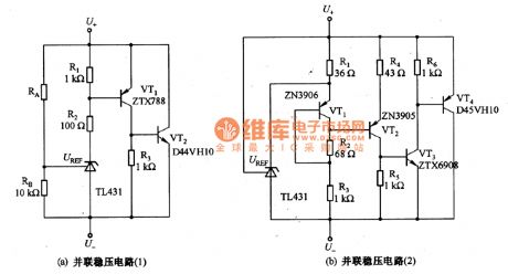
The picture a and b are parallel connection regulating circuits of TL431.The minimum current of regulating circuit (a) is 200μA,maximum current can reach 8A and dynamic range is 91.8dB.The minimum current of regulating circuit (ab) is 1mA,maximum current can reach 8A and dynamic range is 78dB.This circuit can be used as power regulating tube and its main application is as follows.
Fisrt,it is used as parallel connection regulating circuit(high power regulating tube)with large current(8A)and high accuracy.Second,it is used as power supply circuit which changes +5V voltgae into +3.3V/8A.Third,it is used in voltage clamp with large current and high accuracy and thus it can be used as overvoltage protection circuit of DC power supply.TL431 cathode voltage range is main difference of circuit (a)and (b). (View)
View full Circuit Diagram | Comments | Reading(2744)
AN5534 field scanning output integrated circuit
Published:2011/8/24 20:57:00 Author:Christina | Keyword: field scanning, output, integrated circuit
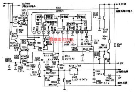
The AN5534 is designed as the field scanning output integrated circuit that is produced by the Panasonic company, and this device can be used in all kinds of domestic and imported color TVs.
1.Features
The AN5534 is composed of the field oscillation sawtooth wave signal generating circuit, the field incentive and output circuit. The internal circuit block diagram and the typical application circuit are as shown in figure 1-18.
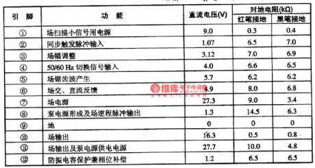
2.Pin functions and data
The AN5534 uses the 12-pin single row DIP package, and it can be used in the ChangHong IR2116N series color TV, the pin functions and data are as shown in table 1-18.
(View)
View full Circuit Diagram | Comments | Reading(2603)
AN5151 monolithic TV signal processing integrated circuit
Published:2011/8/24 22:03:00 Author:Christina | Keyword: monolithic, TV signal, processing, integrated circuit
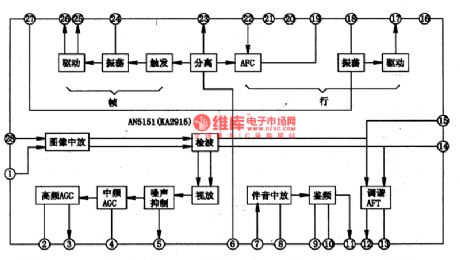
The AN5151 is designed as the monolithic TV signal processing integrated circuit that is produced by the Panasonic company, and it can be used in the 3.5 ~ 5.5 inches small screen TVs.
1.The internal circuit block diagram
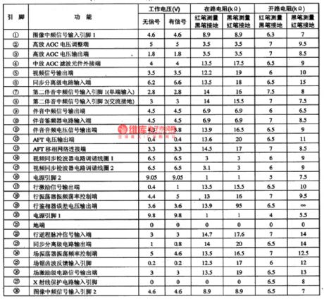
The AN5151 has the functions of image and accompanying sound medium amplification, the AGC medium amplification, the AGC high amplification, AFC, AFT, line and field scanning oscillation. The internal circuit block diagram is as shown in figure 1-16.
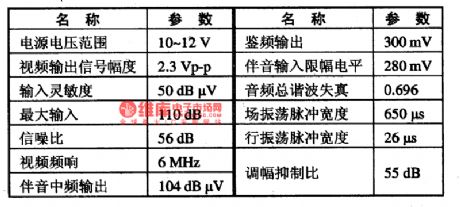
2.The typical technical data
The typical technology parameters of the AV5151 are as shown in table 1-15.
3.The functions and data of pin-5
The AV5151 uses the dual-row 28-pin DIP package, the pin functions and data are as shown in table 1-16.
Tip: The similar products of AN5151 are KA2951, AV5150. The KA2915 can replace the AN5151 directly, the most of functions and pin functions of AV5150 are the same as the AV5151.
(View)
View full Circuit Diagram | Comments | Reading(1651)
Fusible Line Circuit of Beijing Cherokee Light Off-road Vehicle
Published:2011/8/14 8:06:00 Author:Michel | Keyword: Cherokee, Light Off-road Vehicle, Fusible Line Circuit
Third, Fusible Line
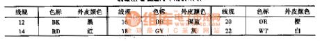
The fusible line protects the line in a circuit system when it is short-circuit.The color code of the fusible line stands for its specification(It is shown as table 26-7).When the fusible line is broken,we have to find out the fault reason.After the fault is completely excluded and it starts to work as usual,the line can be replaced by the same specification fusible line with polyethylene insulation sleeve.
Table: Fusible Line Circuit of Beijing Cherokee Light Off-road Vehicle (View)
View full Circuit Diagram | Comments | Reading(671)
Benchmark Voltage Source Circuit of Zero Temperature Coefficient
Published:2011/7/26 0:01:00 Author:Michel | Keyword: Temperature Coefficient, Voltage Source Circuit
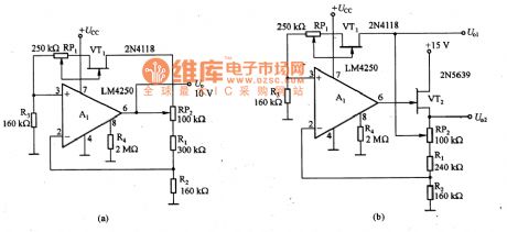
Picture a and b are the benchmark voltage source circuits of zero temperature coefficient.Zero temperature coefficient of benchmark voltage chooses the work point of field effect transistor according to zero temperature coefficient points of UGS-ID characteristic curve. It uses the voltage drop of both ends,which makes the constant current diode of zero temperature coefficient work.Operational amplifier A1 (LM4250) is the same phase work state and its work current is determined by R4.RP1 is used to set benchmark voltage temperature coefficient, it can be chosen between in positive,negative and zero.RP2 is used to adjust the voltage slightly.All the resistor in the circuit needs to choose metalfilmresistor with good temperature characteristic.Picture (b) is different from picture (a) and its A1 input end is connected with VT2 and there are two kinds of output voltgae.
(View)
View full Circuit Diagram | Comments | Reading(854)
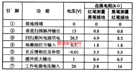
AN5539 field scanning output integrated circuit
Published:2011/8/23 22:38:00 Author: | Keyword: field scanning, output, integrated circuit
The AN5539 is designed as the field scanning output integrated circuit which is composed of the Panasonic company, and it can be used in all kinds of domestic and imported color TVs.
1.Features
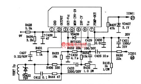
The AN5539 has the field excitation and output circuit and the pump power control circuit. The maximum output current is 2.2Ap-p, the maximum output power is 15W. The typical application circuit of the manifold is as shown in figure 1-19.
2.Pin functions and data
The AN5539 uses the 7-pin single row DIP package, the 5-pin functions and data are as shown in table 1-19.
(View)
View full Circuit Diagram | Comments | Reading(9430)
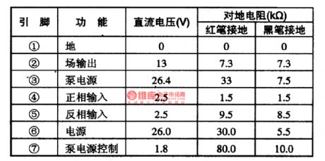
AN5521 field scanning output circuit
Published:2011/8/24 21:11:00 Author:Christina | Keyword: field scanning, output circuit
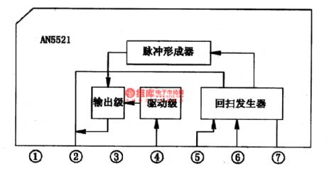
1.Features
The AN5521 is composed of the field scanning pulse forming device, the flyback generator, the driving circuit and the field scanning output circuit, the internal circuit block diagram is as shown in the figure 1-17.
2.Pin functions and data
The AN5521 uses the 7-pin single row DIP package, the pin functions and data are as shown in table 1-17.
(View)
View full Circuit Diagram | Comments | Reading(1244)
Household automatic hand dryer circuit
Published:2011/8/24 21:25:00 Author:Christina | Keyword: Household, automatic, hand dryer
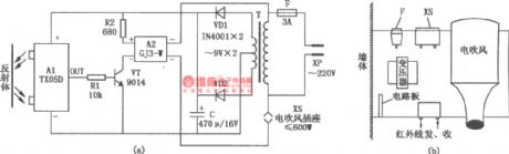
The household automatic hand dryer circuit is as shown in figure (a), it is composed of the infrared reflection switch A1, the AC SSR A2, the hair dryer and the power conversion circuit. After you open the power, the A1 outputs the infrared ray. Because there is no object to reflect the infrared ray, so the OUT port of A1 outputs the low level, the VT cuts off, also the A2, the hair dryer which is connected with the socket XS will not operate. When the hand is below the hand dryer, the infrared ray is reflected by the hand, the OUT port of A1 outputs the high level signal, the VT conducts.
(View)
View full Circuit Diagram | Comments | Reading(5132)
Household automatic faucet composed of the TX05D
Published:2011/8/24 21:39:00 Author:Christina | Keyword: Household, automatic faucet
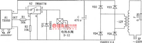
The Household automatic faucet composed of the TX05D is as shown in the figure.
(View)
View full Circuit Diagram | Comments | Reading(948)
The triangle wave and square wave circuit composed of the analog switch
Published:2011/8/24 21:48:00 Author:Christina | Keyword: triangle wave, square wave, analog switch
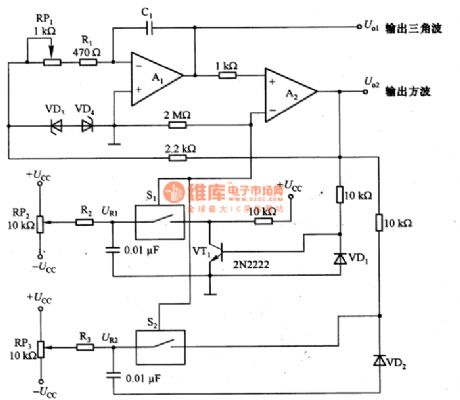
The triangle wave and square wave circuit composed of the analog switch is as shown in the figure. In this circuit, the resistance values of the adjustment potentiometer RP2 and RP3 change the reference voltage UR1 and UR2, so we can change the triangular wave voltage level and amplitude accurately and independently. You can change the resistance value of potentiometer RP1 to change the oscillation frequency of the circuit. The UR1 and UR2 can use the external power supply, if it is used with the D/A converter, they can form the digital wave amplitude control triangulation oscillator. If we assume that the stable voltage of VD3 and VD4 is Uz, the oscillation period T=2(RRP1+R1)C1(UR2-UR1)/Uz+0.7), the 0.7(V) is the positive voltage drop of VD3 or VD4.
(View)
View full Circuit Diagram | Comments | Reading(1216)
Automatic counter composed of the TX05D
Published:2011/8/24 21:52:00 Author:Christina | Keyword: Automatic counter
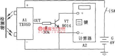
The automatic counter is composed of the TX05D and the pocket calculator. As the figure shows, it can be used in the product automatic counting of the factory production line conveyor belt, the transformer winding circle number automatic counting and the equipment movements automatic counting.
(View)
View full Circuit Diagram | Comments | Reading(770)
The application circuit of the N-type thermocouple
Published:2011/8/23 22:36:00 Author: | Keyword: application circuit, N-type, thermocouple
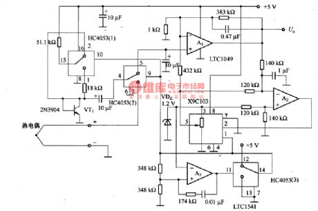
The thermocouple has the strong durability, the good stability and low price. So it can be used in the industry applications. Figure 3-1 is the application circuit of the N-type thermocouple. It uses the compensation circuit and the digital controlled linear circuit of the chopper-stabilized amplifier △UBE cold contact point. So there is no need to adjust the circuit, in the 4-373K thermodynamics temperature range, the output full-scale error of this circuit is +/-3%. When the circuit is connected with the thermocouple sensor, the circuit will changes into the accurate thermodynamics temperature scale thermometer.
In this circuit, the X9C103 is the digital potentiometer, the HC4053(1)-HC4053(3) are the analog switches, A1 uses the LTC1049 operational amplifier, A2 and A3 use the LTCl541 operational amplifier.
(View)
View full Circuit Diagram | Comments | Reading(2220)
24dB/ octave Low-pass Filter Circuit Composed of the Same Parameters (μPC882)
Published:2011/8/10 9:54:00 Author:Felicity | Keyword: Same Parameters, Low-pass Filter
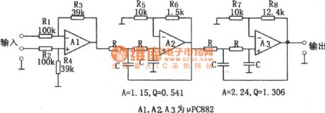
The circuit is 24dB/ octave low-pass filter composed of the filter components of the same parameters. To get the required Q, the open-loop gain of the operational amplifier should be above 1 and the input stage become a 1/2.57 attenuator. This circuit’s feature is the resistance R and capacitor C with decided cutoff frequency fc can reach the same parameters. The parameters of the circuit are determined by cutoff frequency, fc=1/(2πRC) ,and the resistance range is between several to several hundred kΩ and the capacity is above several hundred pF.
(View)
View full Circuit Diagram | Comments | Reading(2216)
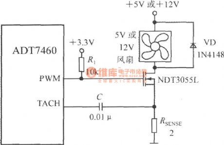
Circuit For Driving A Two-wire Fan (Smart Remote Thermal Fan Controller ADT7460)
Published:2011/8/11 8:04:00 Author:Felicity | Keyword: Two-wire Fan, Smart, Remote, Thermal Fan, Controller
View full Circuit Diagram | Comments | Reading(975)
-18dB/octave Active Low-pass Filter Circuit (RC4558DN)
Published:2011/8/10 7:19:00 Author:Felicity | Keyword: Active, Low-pass Filter
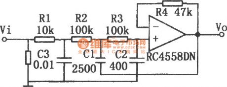
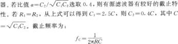
The -18dB/octave active low-pass filter circuit is shown in the figure. This circuit consists of -6dB passive filter and -12dB/octave active filter and the whole circuit is a -18dB/octave active low-pass filter. The passive filter consists of R1 and C3, the active filter consists of R2, R3, C1, C2 and operational amplifier.
(View)
View full Circuit Diagram | Comments | Reading(4389)
Q and Frequency Adjustable Narrow Band Filter (741)
Published:2011/8/10 7:38:00 Author:Felicity | Keyword: Q and Frequency Adjustable, Narrow Band Filter
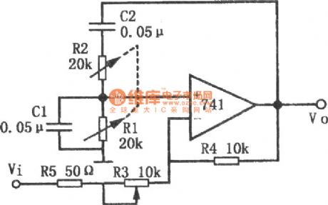
The circuit is an active Q and frequency adjustable narrow band filter. It adopts the form of Wien bridge positive feedback ,but the loop gain is under 1.The character of this circuit is that adjusting Q has no effect on center frequency, because Q only depends on the gain of the circuit.When the gain is 600,Q is 2000; and when the gain is 140,Q is 30. And in the ordinary Wien bridge oscillator, for non-inverting terminal, the gain of the amplifier must above 3 to oscillate, but in this circuit the gain of the amplifier is below 3. (View)
View full Circuit Diagram | Comments | Reading(1198)
The Circuit of Active High-Pass Filter With Sharp Cutoff Performance (RC4558DN)
Published:2011/8/10 7:58:00 Author:Felicity | Keyword: Active, High-Pass Filter, Sharp Cutoff Performance
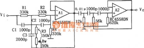
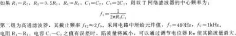
Active high-pass filter with sharp cutoff performance is shown in this circuit. To improve the frequency characteristic around cutoff frequency fc of high-pass filter, in this circuit a high-pass filter and a band-stop filter are connected in series to improve the frequency characteristic of the high-pass filter. The first stage in this circuit is band-stop filter consists of double-T network and load resistance R4, composing band-pass filter that gain descends in low frequency. To increase the value of Q, there is a bootstrapping at the end of the double-T network. (View)
View full Circuit Diagram | Comments | Reading(2803)
| Pages:120/471 At 20101102103104105106107108109110111112113114115116117118119120Under 20 |
Circuit Categories
power supply circuit
Amplifier Circuit
Basic Circuit
LED and Light Circuit
Sensor Circuit
Signal Processing
Electrical Equipment Circuit
Control Circuit
Remote Control Circuit
A/D-D/A Converter Circuit
Audio Circuit
Measuring and Test Circuit
Communication Circuit
Computer-Related Circuit
555 Circuit
Automotive Circuit
Repairing Circuit