
Index 118
Touching monolithic flasher - buzzer circuit diagram
Published:2011/9/7 21:48:00 Author:Lucas | Keyword: Touching monolithic flasher , buzzer
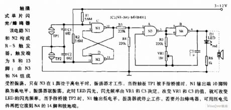
In the circuit, N1, N2 constitute the RS flip-flop, and the trigger end is pin 8 and 13; N3, N4 form the controlled oscillator, only when N3's pin 1 is high, the oscillator works. When the finger touching pad TP1 is bridging, N1 output's pin 10 turns to high level, the oscillator will oscillate, then the LED flashes, and the flash frequency is determined by the VR1 and C3. Changing the value of VR1 and C3, we can change the LED flashing frequency. When the finger is bridged to TP2, N1 output is low, the oscillator will stop working. If needs the external buzzer, then you can connect it to N4's pin 14 and the ground by piezoelectric components.
(View)
View full Circuit Diagram | Comments | Reading(1719)
The trigger circuit diagram for teaching demonstration
Published:2011/9/7 22:34:00 Author:Lucas | Keyword: trigger , teaching demonstration
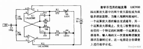
The two amplifiers in LM3900 quad op amp form the bistable multivibrator. When the input is grounded, the output of one op amp becomes conduction, and the other op amp stops, and light-emitting diode indicates which op-amp is conduction at any given moment. Input is grounded again, the flip-flop's state flips over. This circuit is suitable for teaching demonstration in the classroom.
(View)
View full Circuit Diagram | Comments | Reading(1066)
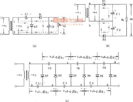
Double Voltage Boost Circuit Constituted By In Gate Circuit(CD4069)
Published:2011/9/6 5:19:00 Author:Felicity | Keyword: Double Voltage, Boost Circuit, In Gate Circuit
View full Circuit Diagram | Comments | Reading(781)
Electronic Double Voltage Boost Circuit
Published:2011/9/6 5:15:00 Author:Felicity | Keyword: Electronic, Double Voltage, Boost Circuit
View full Circuit Diagram | Comments | Reading(742)
Doubler Rectifier Circuit
Published:2011/9/6 5:21:00 Author:Felicity | Keyword: Doubler, Rectifier
View full Circuit Diagram | Comments | Reading(604)
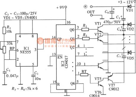
The clock circuit for driving trigger flashing circuit
Published:2011/8/29 2:44:00 Author:Lucas | Keyword: clock circuit , driving trigger flashing
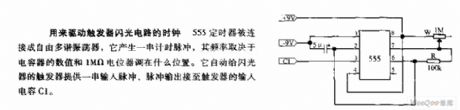
555 timer is connected as free multivibrator, which generates a string of timing pulses, and the frequency depends on the value of the capacitor and the adjusting position of 1MΩ potentiometer. It automatically provides a string of input pulse to the flasher trigger, and the pulse output is connected to the trigger input capacitor C1.
(View)
View full Circuit Diagram | Comments | Reading(570)
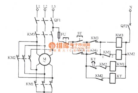
Boiler induced draft fan circuit (1)
Published:2011/9/5 21:53:00 Author:TaoXi | Keyword: Boiler, induced draft fan
View full Circuit Diagram | Comments | Reading(936)
Pulse sound and light display circuit diagram
Published:2011/9/5 3:51:00 Author:Lucas | Keyword: Pulse , sound and light , display
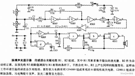
Sensor is composed of the photosensitive resistors R1, R2, of which R1 is used to collect the amount of light transmission from the tip of finger, R2 is an automatic correction device. The resistors R1, R2 are transferred to equal conditions in advanced, the interference will generate the same resistance changes on the R1, R2, so the error caused by the work environment will cancel by each other. Shaping amplifier uses CD4069 to form the conventional 6-stage amplifier circuit. CD4011 forms the audio oscillator, piezoelectric sound, light emitting diode indicator.
(View)
View full Circuit Diagram | Comments | Reading(1393)
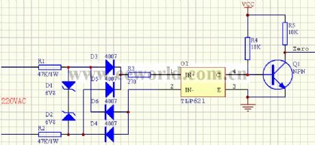
Recognized zero-crossing pulse circuit
Published:2011/9/6 1:05:00 Author:TaoXi | Keyword: Recognized, zero-crossing pulse
View full Circuit Diagram | Comments | Reading(890)
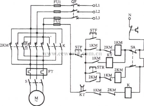
Boiler coal conveyor circuit
Published:2011/9/6 1:06:00 Author:TaoXi | Keyword: Boiler, coal conveyor circuit
View full Circuit Diagram | Comments | Reading(1367)
Beijing Cherokee car technical specification circuit diagram
Published:2011/8/27 1:37:00 Author:Nancy | Keyword: Cherokee, car technical specification
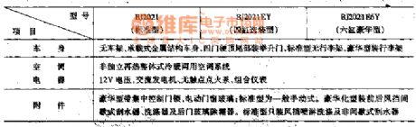
The crankshaft position sensor, synchronous signal sensors, blend air manifold absolute pressure sensor (MAP), cooling fluid temperature sensor, and fire temperature degrees sensors, throttle position sensor, the wheel speed sensors, oxygen sensors, storage battery voltage signal, the ignition switch, air conditioning switch, power steering, braking switch analog, pulse signal and switch signals are all necessary input signals of the computer. (View)
View full Circuit Diagram | Comments | Reading(539)
Basic timing circuit diagram formed by NE555
Published:2011/8/27 1:33:00 Author:Nancy | Keyword: Basic timing
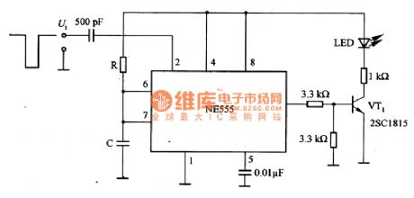
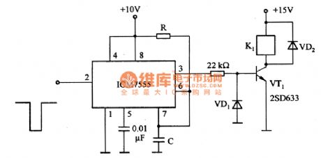
Figure 1 is the basic timing circuit diagram formed by NE555. Figure 1 (a) is the basic timing circuit diagram formed by NE555. In the circuit, if a trigger pulse is added to the pin 2 as shown in the figure 1, then there must be a certain time interval pulse in pin 3 output, the interval is T ~ RC, which is amplified by VT1 to drive the light-emitting diode LED in the related circuit in Figure 1.
Figure 1 (b) is the timing circuit formed by CMOS (ICM7555). It adopts CMOS and has high impedance, the setting time can be greatly extended, for example, it can be used in the timer of a few minutes. In the figure, R is ranging from lkΩ to lOOMΩ, C is ranging from 1OOpF to 10000μF. (View)
View full Circuit Diagram | Comments | Reading(672)
0M1032--Microcomputer dialing integrated circuit diagram
Published:2011/8/27 1:15:00 Author:Nancy | Keyword: Microcomputer, dialing, integrated circuit
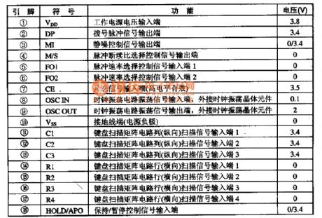
0M1032 series microcomputer dialing integrated circuit is widely used in all kinds of communication telephones.
0M1032 integrated circuit contains dialing signal processing circuit, static noise control circuit, key switch encode and decode circuit. The IC adopts 18-pin DIP structure, the pin function and data is shown as the table.
(View)
View full Circuit Diagram | Comments | Reading(558)
High resolution quadruple frequency subdivision circuit diagram
Published:2011/9/6 21:03:00 Author:Vicky | Keyword: high resolution, quadruple frequency , subdivision circuit
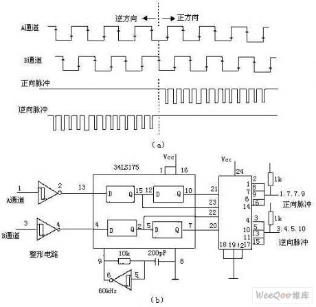
The above picture is a circuit of quadruple frequency which can not only avoid the false pulse, but also improve the high resolution. Here, it adopts a memorable D-type trigger and clock generator circuit. As shown in picture 4, every channel has two D-type triggers in serial, so that, during the interval of the clock pulse, the two Q ends (such as the corresponding pin2 and pin7 of 74LS175 in channel B) retain the input state of the former two periods. If the two are the same, it means there is no change in the clock interval; otherwise, the change of direction can be judged by the relationship within, and therefore the output pulse of forward direction or reverse direction is generated. (View)
View full Circuit Diagram | Comments | Reading(953)
Diagram of two filter circuits used for AM broadcast interference
Published:2011/9/6 21:00:00 Author:Vicky | Keyword: filter circuit, AM broadcast interference
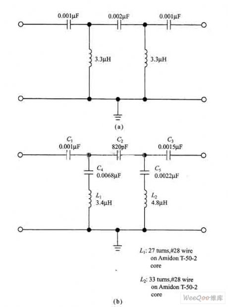
AM reflecting filter in the picture (a) can be composed of common disk-type ceramic capacitor, silver capacitor, and Panasonic V series polyester capacitor. Though it is better to use digital capacitance meter or capacitance bridge to match with, an allowance of 5 percent for the component can still meet the satisfaction. If silver capacitance is used, it is better to use 1000pF (0.001ptF) capacitance, and the 0.002ptF capacitance can use two 0.001pF capacitances in serial (C1 and C3)。 The average inductance of the circuit is 3.3μH. It can use either isolated regular magnetic chip inductance or non-isolated annular magnetic chip inductance. (View)
View full Circuit Diagram | Comments | Reading(921)
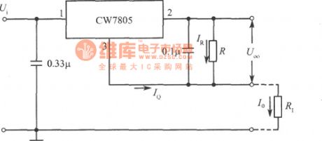
CW7805 constant current source circuit
Published:2011/8/26 3:23:00 Author:chopper | Keyword: constant current source
View full Circuit Diagram | Comments | Reading(1248)
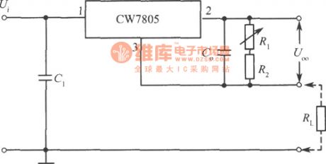
CW7805 constant current source circuit with adjustable output current
Published:2011/8/26 3:24:00 Author:chopper | Keyword: constant current source, adjustable, output current
View full Circuit Diagram | Comments | Reading(1018)
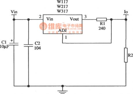
constant current source application circuit of Wll7,W217,W317
Published:2011/8/26 3:25:00 Author:chopper | Keyword: constant current source, application circuit
View full Circuit Diagram | Comments | Reading(655)
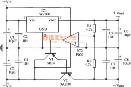
application circuit of regulated power supply in tracking mode of W7800
Published:2011/8/26 3:28:00 Author:chopper | Keyword: application circuit, regulated power supply, tracking mode
View full Circuit Diagram | Comments | Reading(623)
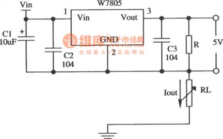
application circuit of constant current source of W7805
Published:2011/8/26 3:28:00 Author:chopper | Keyword: application circuit, constant current source
View full Circuit Diagram | Comments | Reading(1007)
| Pages:118/471 At 20101102103104105106107108109110111112113114115116117118119120Under 20 |
Circuit Categories
power supply circuit
Amplifier Circuit
Basic Circuit
LED and Light Circuit
Sensor Circuit
Signal Processing
Electrical Equipment Circuit
Control Circuit
Remote Control Circuit
A/D-D/A Converter Circuit
Audio Circuit
Measuring and Test Circuit
Communication Circuit
Computer-Related Circuit
555 Circuit
Automotive Circuit
Repairing Circuit