
Index 105
TD6301I(2)C bus control display drive IC diagram
Published:2011/9/13 2:28:00 Author:Rebekka | Keyword: bus control display drive
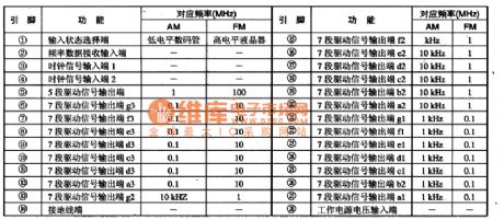
TD6301 is an I (2) C bus control display drive integrated circuit. It is widely used in low-voltage high-grade players and other audio equipment, car audio. TD6301 IC contains 3 groups of 7-segment display drive circuits and the input state selection circuit. The IC uses 28-pin plastic dual in-line structure, the IC 5 pin functions and data arelisted in Table 2. The pin functions and data of TD630lAP IC are shown in table.
(View)
View full Circuit Diagram | Comments | Reading(690)
Panasonic NV-450 VCR system modification circuit diagram
Published:2011/8/22 3:26:00 Author:Jessie | Keyword: Panasonic , VCR system , modification circuit
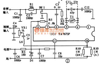
Panasonic NV-450 VCR system modification circuit diagram is shown as the chart. TA7673P is a special radio frequency modulation integrated circuit, and its sound carrier frequency is 5.5 MHz. T1 and Cllare connected tothe pin 4andpin5 of rf modulation integrated circuits, which can determine the oscillation frequencyof voices. Therefore, the method ofchanging sound carrier frequency from 5.5 MHz to 6.5 MHz is: change C11 of LC resonant circuit from 47p to 27p, then connect VCR with television, let video replay a box of good video, then watch videos as side trimming the magnetic cores of Tl to make the sound best. (View)
View full Circuit Diagram | Comments | Reading(2451)
Electronic transformer with dependable performance
Published:2011/4/14 6:52:00 Author:may | Keyword: Electronic transformer, dependable performance
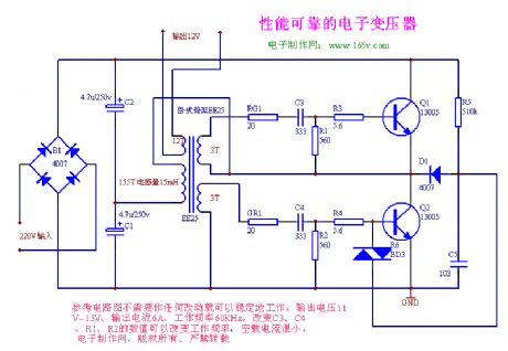
The circuit can steady work to consult the circuit diagram with no changes. Output voltage is 11V-13V, output current is 6A, working frequency is 60kHz. It can change working frequency by changing the numerical value of C3, C4, R1, R2. Its no-load current is very small.
(View)
View full Circuit Diagram | Comments | Reading(4409)
Parallel push-pull voltage changer
Published:2011/4/14 6:52:00 Author:may | Keyword: Parallel push-pull, voltage changer
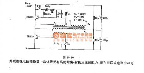
This circuit adopts two capacitors with 100μF to make up man-made star point. When shutting off, this circuit can prevent transistor from destroying by high back voltage. Using regulation resistance with 50Ω can adjust the turn on level of transistor. The usage of 0.1μF capacitor is toincrease thespeed of on-off.
The data of transformer:
Winding np= 160turns, 0.5mm copper lacquered wire
nr= 13turns, 0.2mm copper lacquered wire
ng= 1300turns, 0.15mm copper lacquered wire
The transistor in parallel push-pull transformer should have the ability of high withstand collector-emitter back voltage.
(View)
View full Circuit Diagram | Comments | Reading(767)
Voltage changer controls frequency by blocking oscillator
Published:2011/4/14 6:50:00 Author:may | Keyword: Voltage changer, blocking oscillator
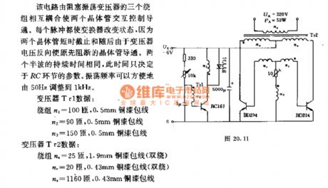
This circuit is mutual coupling by three windings of blocking oscillator transformer. This let two transistors in turns tocontrol and turn on. Each pulse can change the state of transformer, because two transistors cut off in a short time, and, later the transistor which is cutting off before is turn on because the voltage of transformer is reversing. The duration of two half-wave is the same. This time depends on the parameter of RC link. The oscillation frequency can easily adjust from 50Hz to 1kHz.
Data of transformer Tr1:
Wing n1= 100turns, 0.5mm copper enameled wire
n2= 90turns, 0.5mm copper enameled wire
n1= 150turns, 0.5mm copper enameled wire
Data of transformer Tr2:
Wing na= 25turns, 1.9mm copper enameled wire (double wrap)
nr= 20turns, 0.43mm copper enameled wire (double wrap)
na= 1160turns, 0.43mm copper enameled wire (View)
View full Circuit Diagram | Comments | Reading(1282)
Switching supply driving transformer
Published:2011/4/14 6:48:00 Author:may | Keyword: Switching supply, driving transformer
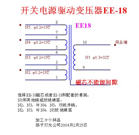
The introduction of winding coiling of high frequency transformer (switching supply driving transformer)
Switching supply driving transformer EE-18
We can choose EE-18 magnetic core or the assorted skeleton of EI-18.
One can put N1 and others winding in insulating barrier,
N2, N3 double winding along with N4, N5.
N2, N3, and N4, N5 is in insulating barrier. (View)
View full Circuit Diagram | Comments | Reading(695)
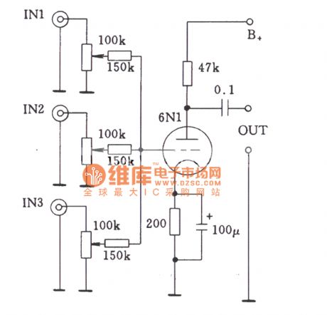
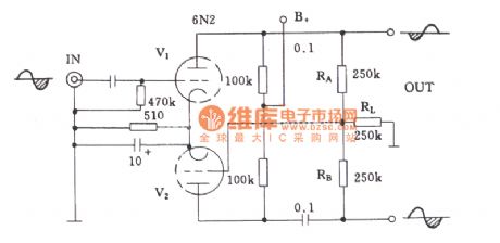
Single-stage multi-channel input circuit of tube by coupling resistor
Published:2011/10/14 1:44:00 Author:Ecco | Keyword: Single-stage , multi-channel input, coupling resistor
View full Circuit Diagram | Comments | Reading(666)
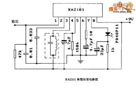
KA2181 application circuit diagram
Published:2011/10/16 21:57:00 Author:Ecco | Keyword: application circuit
View full Circuit Diagram | Comments | Reading(1060)
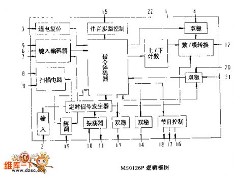
M50126P logic frame circuit diagram
Published:2011/10/16 22:26:00 Author:Ecco | Keyword: logic frame
View full Circuit Diagram | Comments | Reading(699)
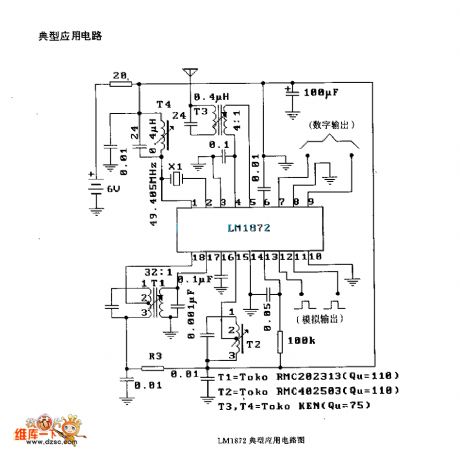
LMl872 application circuit diagram
Published:2011/10/16 22:25:00 Author:Ecco | Keyword: application circuit
View full Circuit Diagram | Comments | Reading(579)
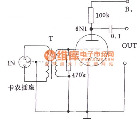
Low-impedance input circuit diagram of tube
Published:2011/10/14 1:39:00 Author:Ecco | Keyword: Low-impedance input, tube
View full Circuit Diagram | Comments | Reading(683)
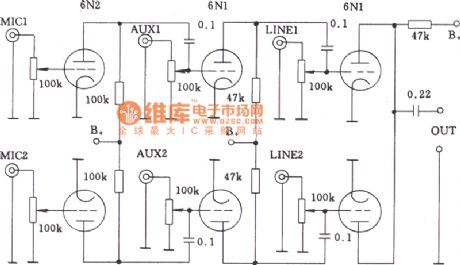
Multi-channel audio input mixing circuit of tube
Published:2011/10/14 1:52:00 Author:Ecco | Keyword: Multi-channel, audio input mixing
View full Circuit Diagram | Comments | Reading(724)
Common-anode loaded inverter circuit of tube
Published:2011/10/14 1:50:00 Author:Ecco | Keyword: Common-anode loaded inverter
View full Circuit Diagram | Comments | Reading(696)
The shape circuit of common potentiometer
Published:2011/10/14 1:42:00 Author:Ecco | Keyword: shape, common potentiometer
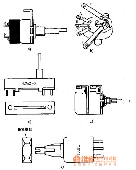
a). b): potentiometer with switch
c): Slide potentiometer
d): asynchronous different double-axis potentiometer
e): locking-type potentiometer (View)
View full Circuit Diagram | Comments | Reading(954)
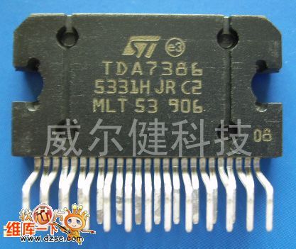
TDA7386 IC
Published:2011/10/14 2:03:00 Author:Ecco
View full Circuit Diagram | Comments | Reading(1613)
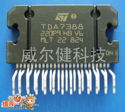
TDA7388 IC
Published:2011/10/14 2:03:00 Author:Ecco | Keyword: IC
View full Circuit Diagram | Comments | Reading(3907)
A super enhanced video circuit
Published:2011/10/14 2:14:00 Author:Ecco | Keyword: super enhanced video
View full Circuit Diagram | Comments | Reading(576)
Common-mode filter circuit diagram
Published:2011/10/14 2:17:00 Author:Ecco | Keyword: Common-mode filter
View full Circuit Diagram | Comments | Reading(681)
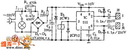
555 touching desk lamp switch circuit diagram
Published:2011/10/16 21:46:00 Author:Ecco | Keyword: 555 , touching desk lamp
View full Circuit Diagram | Comments | Reading(727)
DGK1 three-phase asynchronous motor controller circuit
Published:2011/10/14 3:13:00 Author:Ecco | Keyword: three-phase asynchronous, motor controller

View full Circuit Diagram | Comments | Reading(1251)
| Pages:105/471 At 20101102103104105106107108109110111112113114115116117118119120Under 20 |
Circuit Categories
power supply circuit
Amplifier Circuit
Basic Circuit
LED and Light Circuit
Sensor Circuit
Signal Processing
Electrical Equipment Circuit
Control Circuit
Remote Control Circuit
A/D-D/A Converter Circuit
Audio Circuit
Measuring and Test Circuit
Communication Circuit
Computer-Related Circuit
555 Circuit
Automotive Circuit
Repairing Circuit