
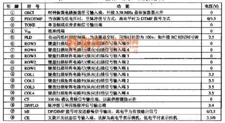
Index 115
High-speed monostable circuit one
Published:2011/9/14 8:00:00 Author:nelly | Keyword: High-speed, monostable
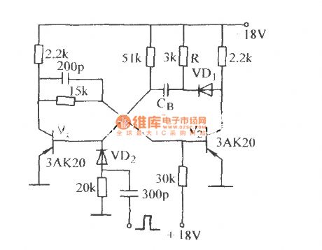
View full Circuit Diagram | Comments | Reading(673)
VRS51L3074 one of electronic clock design circuit diagram
Published:2011/9/14 9:14:00 Author:nelly | Keyword: electronic clock, design
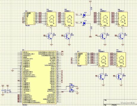
Circuit description: 1, Using common cathode LED; 2, 74LS48 controls LED to show the number, the triode controls the display LED. It adopts dynamic display; 3, With temperature diaplay function; 4, setting button to set clock; 5, The display of year, month, day will be added next. It uses 595 to control, then it can save the using of IO port.
(View)
View full Circuit Diagram | Comments | Reading(1218)
Practical Technology Circuit Diagram for Digital Integrated Circuit
Published:2011/9/13 0:11:00 Author:Zoey | Keyword: Practical Technology, Digital, Integrated Circuit
1.Time fordata setup and maintainmentDigital Circuit mainly refers to synchronouscircuits , which means by using a clock, part of the circuit or all circuits can worksynchronously.synchronouscircuits usually adoptD trigger or J-Ktrigger tolatch the data. Using these triggers, we should pay attention to the latched signal and clock timing, if thereis anyproblem, it will cause circuit malfunction. Figure a, b, c refer to the time for data setup ts and maintainment th. Trigger D uses the clock edge to read the data input and output. Before the ascending edge appears, the data should be setup. This time margin is ts. Afer the ascending edge appears, the data needs to be maintained for some time, this time margin is th.The higher IC's working speed, the shorter time is required.
In practical, if ts and th are not long enough, the trigger will be in a multi-valued state, that is, in ameta-stable state,which means theinput processwillhave along delay time, the level will not be determined, and the trigger will havemalfunction.
(View)
View full Circuit Diagram | Comments | Reading(643)
Thermocouple temperature system simulation circuit
Published:2011/9/12 21:17:00 Author:John | Keyword: Thermocouple temperature system
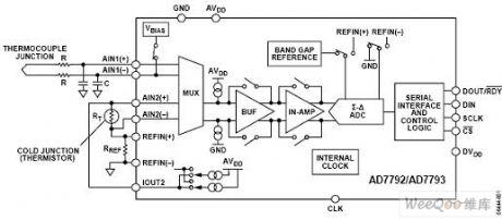
Temperature on the cold junction is measured by the use of resistance temperature detectors (RTD) or thermistor (shown in the RT). The resistance for these two devices changes along with the temperature. On-chip current source provides the required excitation current. In this measurement configuration, a ratio is used, that is, the ADC reference voltage source and the precision resistor use the same excitation current. A ratio configuration enables the temperature measurement on the cold junction to be independent from the excitation current, because the change of excitation current can lead to same changing amount of the voltage generated by the sensor and that generated by the precision resistor. Therefore, there is no effect on analog digital conversion. (View)
View full Circuit Diagram | Comments | Reading(2195)
SANLIXIN Intergrated Solenoid
Published:2011/7/11 7:58:00 Author:Michel | Keyword: Intergrated Solenoid
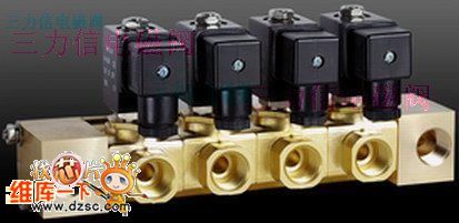
Welcome to download!This information is from www.dzsc.com. (View)
View full Circuit Diagram | Comments | Reading(847)
Anti-EMI Circuit
Published:2011/9/13 5:45:00 Author:Michel | Keyword: Anti-EMI
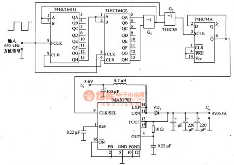
Theanti-EMI circuit is shown as above. MAX1703 is dc/dc boost converter, the input is 3.6 V, output is 5 V / 0.5 A.External random noise (PN) generating circuit provides the clock signal for 9 feet of the converter. In the wide frequency range, the PN generating circuit reduces EMI power density by extending interference frequency.PN generating circuit consists of 74HC164 and74HC74.74HC164 is eight shift register and it feedbacks through the different or a gate G1 and G2.PN signal is output by G2 and its rating frequency is 650kHZ and it is composed of repeatting 0 and 1 . The experimental measurement shows that frequency power density peak reduces to 15dB when it's around 300 kHZ and the efficiency of the converter remains unchanged except PN generating circuit adpots 9mA current from the converter. (View)
View full Circuit Diagram | Comments | Reading(772)
Meter-copy Device
Published:2011/9/13 5:51:00 Author:Michel | Keyword: Meter-copy
Micro meter-copy device changes electric meter into electrical signals via special camera images and it is transfered to LCD display via transmission lines.Special cameras and LCD monitor are connected together via adjustable aluminum alloy bars.Meter reading electrician can adjust aluminum alloy bars and make the top special cameras aim at electric meter so that he can see the electric meter degree in the bottom of the LCD monitor.Micro LCD visual meter-copy device isespecially designed according to the meter's measuring boxes. It consists of sunshades, adjustable auxiliary illuminant and iminiature camera etc.
(View)
View full Circuit Diagram | Comments | Reading(947)
MAX8790 Typical Application Circuit
Published:2011/9/13 5:54:00 Author:Michel | Keyword: Typical, Application Circuit
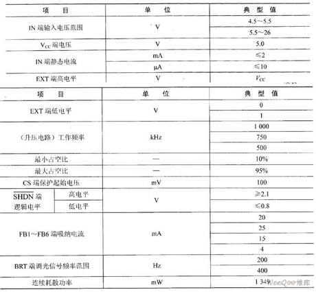
MAX8790 is producedby MAXIM corporation of U.S.A .MAX8790 is designed for the white driving circuit which uses LED backlighting as the light source array LCD display (LCD) degsign.It uses the current model boost to drive 6 groups of LED and it can provide fixed 20mA or adjustable 15~25mA current to every group of LED.Current is adjusted by stepping control mode, each way current's precision can be controlled between about ±1.5%.
AX8790 can use DPWM (digital adjust way) or Analoge stats + DPWM (simulated adjusting mode of linear two ways) to adjust LED brightness。And the regulation range can reach 100∶1. (View)
View full Circuit Diagram | Comments | Reading(618)
The Xiaoshentong XQB20-A washing machine circuit principle diagram
Published:2011/9/12 21:53:00 Author:Christina | Keyword: Xiaoshentong, washing machine, principle diagram
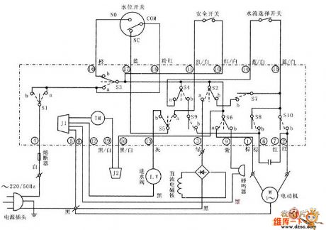
The Xiaoshentong XQB20-A washing machine circuit principle diagram is as shown in the figure:
(View)
View full Circuit Diagram | Comments | Reading(4149)
0M8839PS-K9G216 Digital monolithic small signal processing integrated circuit diagram
Published:2011/9/13 19:47:00 Author:Nancy | Keyword: small signal processing , integrated circuit
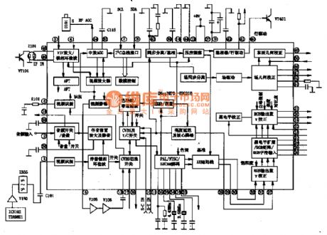
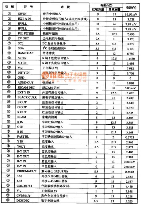
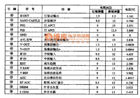
The 0M8839PS-K9G216 is a new generation of monolithic TV V, C, D processing integrated circuit of Philips (a product of the subsidiary in Taiwan). It is widely used in all kinds of a new generation of digital big TV screens.
1. The function and characteristics The 0M8839PS-K9G216 integrated circuit contains a multi system PLL medium frequency demodulation circuit, 4.5-6.5 MHz multi format FM sound intermediate frequency demodulation circuit, self-adjusting PAL/NTSC/SECAM color decoder, 1 line baseband delay line, comb filter, dynamic skin color blue enhance correction circuit, line synchronous controlled by double loop, line/field oscillation and efficient line/field excitation circuitry and east/west pulvinar calibration pulse output and some other units. (View)
View full Circuit Diagram | Comments | Reading(990)
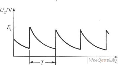
Sequence timer diagram composed by NE555
Published:2011/9/13 19:48:00 Author:Nancy | Keyword: Sequence timer
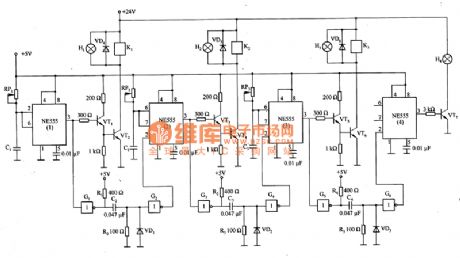
Figure 1 is the sequence timer diagram composed by NE555. The timer can set time any time when the power is connected, break and control the external system to work. In the circuit, K1-K3 are relays used to control the corresponding system to work, adjust the resistance of the RP1-RP3, which can change the break time of the relay. The pin 2 and 6 of NE555(1) connected together, when the power is connected, if the NE555(1) works, C1 charges instantaneously and the charging current flows through pin 2 to C1. At the same time, a waveform output from the pin 3 of NE555(1) forms a trigger pulse after color processed by the G1, which is added to the pin 2 of NE555(1) and make it work. (View)
View full Circuit Diagram | Comments | Reading(2418)
reference voltage circuit composed by LM4130
Published:2011/8/25 7:43:00 Author:Nancy | Keyword: reference voltage
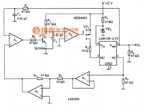
The reference voltage circuit composed by LM4130 is shown as the figure. In the circuit, the temperature controller formed by A1~A4 makes the junction temperature of LM3140 keep at 75 ℃ and the external temperature of LM3140 change between 85 and 40 ℃, and the range is 125 ℃, but the internal temperature is 85 and 40 ℃, the range is narrower 6.25 times than that of external temperature, which make the temperature coefficient of the output reference voltage of LM4130 improved significantly.
The thermostat is formed by the LM4130 chip surface, and the empty pins (pin 1 and 3) used to adjust the temperature coefficient become a part of the temperature control loop, so the thermostat doesn't use heat shield, and has no special requirements to the mechanical device and heater. In addition, all the components can be installed in surface, and the space requirement to the substrate is least. (View)
View full Circuit Diagram | Comments | Reading(1250)
Repeat timing circuit formed by PUT
Published:2011/8/25 7:42:00 Author:Nancy | Keyword: PUT, repeat timing circuit
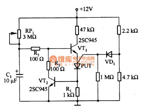
Figure 1 is the repeat timing circuit formed by PUT. It is a repeat timing circuit composed by one PUT, two transistors and a diode, which is not effected by the change of the the power supply voltage and the temperature and has long-term stability. When PUT conducts, the anode current is shunted by the transistor VT2, the base current of VT1 is cut off and the PUT resets. The negative temperature coefficient of VD1 makes a temperature compensation to the offset voltage of PUT. The RP1 resistance is larger, which is 3 MΩ, so we should choose the gold/film resistor with small temperature effect and C1 selects a knob capacitor with small leakage current. (View)
View full Circuit Diagram | Comments | Reading(755)
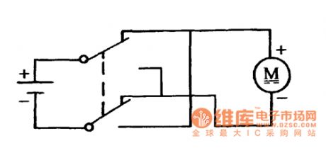
DC motor forward/reverse circuit controlled by the double pole double throw switch
Published:2011/8/25 7:40:00 Author:Nancy | Keyword: DC motor, forward/reverse circuit, double pole double throw switch
View full Circuit Diagram | Comments | Reading(3217)
The simplest multivibrator circuit composed of the photocoupler
Published:2011/8/25 7:39:00 Author:Nancy | Keyword: multivibrator , photocoupler
The figure1 is the simplest multivibrator circuit composed by the photocoupler. When the power is on, because the voltage across C can't break and the value of R is greater than RL, the power supply Ec is mainly added on the R, the electric potential at point F is very low, LED is at off state, with the charging voltage of capacitor increasing, the electric potential at point F is increasing gradually to a certain value to make LED conduct and flash, and make phototriode conduct and saturate, the output voltage jumps close to the power supply, but the left charge of the capacitor discharges quicky through phototriode and LED. (View)
View full Circuit Diagram | Comments | Reading(654)
The remote temperature measurement circuit composed of intelligent temperature sensor and external buffer
Published:2011/9/10 22:01:00 Author:Felicity | Keyword: remote temperature measurement circuit, intelligent temperature sensor, external buffer
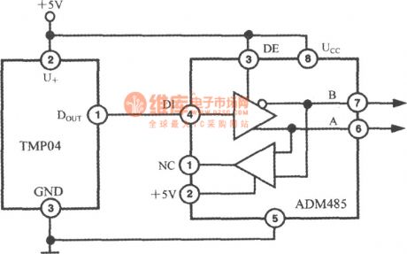
During the remote temperature measurement, TMP03/04 has a big advantage over analog output temperature sensor. It’s becausethe output is digital signal which has a better performance of resisting disturbance. The proportion of T1/T2 cannot be affected between long distance transmission and an AD485 type RS-485 differential line drive can be added if necessary as shown in the circuit diagram. This circuit can transmit temperature signal over 1200m. The time delay caused by emitter and receiver in ADM485 is 5ns and won’t affect T1, T2. (View)
View full Circuit Diagram | Comments | Reading(958)
Temperatur/Frequency conversion circuit ( low power programmable integrated temperature controller TMP01)
Published:2011/9/10 22:00:00 Author:Felicity | Keyword: Temperatur/Frequency conversion circuit, low power, programmable , integrated temperature controller
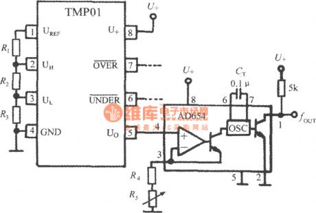
During long distance transmission, temperature signal can be converted into frequency signal and the circuit is shown in the figure. The AD654 voltage/frequency convertor (VFC for short) is adopted in the circuit which can suppress the noise disturbance and voltage fluctuation. When the precision of U/f conversion is enough, the output signal can stand for the test temperature which determined as follow. And CT is the capacity of the external timing capacitor of the internal oscillator. The frequency can be corrected by adjusting R5.
(View)
View full Circuit Diagram | Comments | Reading(1189)
Parallel output digital temperature transmitter circuit (integrated temperature sensor with voltage output LM35)
Published:2011/9/10 21:59:00 Author:Felicity | Keyword: Parallel output, digital temperature transmitter , integrated temperature sensor, voltage output

View full Circuit Diagram | Comments | Reading(1562)
Serial output digital temperature transmitter circuit (integrated temperature sensor with voltage output LM35)
Published:2011/9/10 22:01:00 Author:Felicity | Keyword: Serial output, digital temperature transmitter , integrated temperature sensor, voltage output
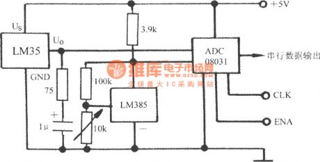
The output of LM35 is analog quantity and can get digital quantity output by A/D converter (ADC). A serial output digital temperature transmitter circuit with ADC08031 is shown in the figure and the range is +128℃ .The CLK and ENA in the figure are Clock terminal and Enable terminal.
(View)
View full Circuit Diagram | Comments | Reading(1697)
Output adapter circuit of LM35 series temperature sensor---- High precision 100 fields LED bar diagram display meter circuit
Published:2011/9/10 22:01:00 Author:Felicity | Keyword: temperature sensor, Output adapter circuit , High precision , 100 fields LED bar diagram display
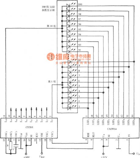
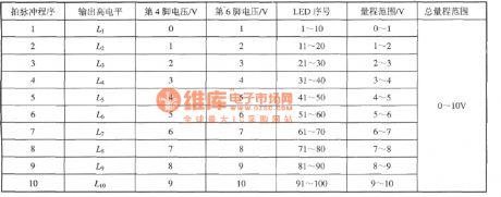
High precision 100 fields LED bar diagram display meter circuit is shown. This meter adapts the output circuit of LM35 series temperature sensor. For example, to build up a 0~10oC thermometer , the division value can be 0.1℃. The circuit contains CH261 and LM3914. The work program of LM3914: (View)
View full Circuit Diagram | Comments | Reading(1898)
| Pages:115/471 At 20101102103104105106107108109110111112113114115116117118119120Under 20 |
Circuit Categories
power supply circuit
Amplifier Circuit
Basic Circuit
LED and Light Circuit
Sensor Circuit
Signal Processing
Electrical Equipment Circuit
Control Circuit
Remote Control Circuit
A/D-D/A Converter Circuit
Audio Circuit
Measuring and Test Circuit
Communication Circuit
Computer-Related Circuit
555 Circuit
Automotive Circuit
Repairing Circuit