
Index 107
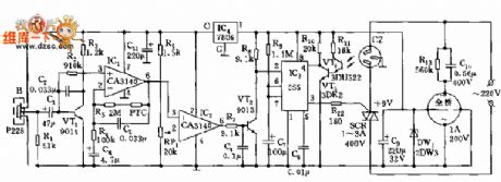
Pyroelectric infrared sensor and light control delay saving socket circuit
Published:2011/10/14 3:11:00 Author:Ecco | Keyword: Pyroelectric infrared sensor , light control , delay saving socket
View full Circuit Diagram | Comments | Reading(759)
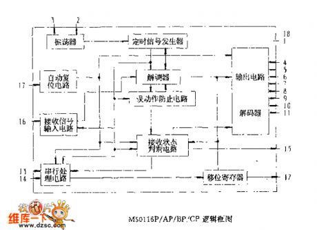
M50116P/AP/BP/CP logic box circuit
Published:2011/10/14 3:08:00 Author:Ecco | Keyword: logic box
View full Circuit Diagram | Comments | Reading(768)
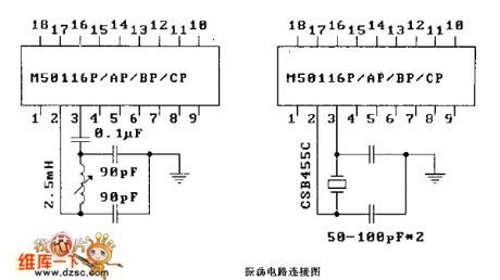
M50116P/AP/BP/CP oscillator connection circuit diagram
Published:2011/10/14 3:07:00 Author:Ecco | Keyword: oscillator connection
View full Circuit Diagram | Comments | Reading(738)
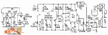
Shielding infrared automatical switching tap circuit
Published:2011/10/14 3:05:00 Author:Ecco | Keyword: Shielding infrared , automatical switching tap
View full Circuit Diagram | Comments | Reading(840)
Optical isolation circuit diagram using as scanner
Published:2011/9/15 21:21:00 Author:Rebekka | Keyword: Optical isolation , scanner
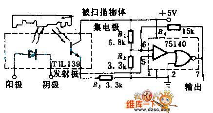
The circuit includes a TIL139 source / detector assembly and the 75140 line receiver. It can be used to makeresponse to reflected light or interruption light. With 5V power supply, the output is standard TTL level.Itinserts the 500Ω potentiometer between R1 and R2 to make the sensitivity be adjusted, then75140's pin(7)is connected to (3) and itgets the output from (1). You can reverse the output polarity. (View)
View full Circuit Diagram | Comments | Reading(1052)
Optical isolation circuit for isolating AC hum sound
Published:2011/9/15 21:25:00 Author:Rebekka | Keyword: Optical isolation , AC hum sound
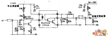
In the TV's audio feed-in line, it uses optical isolators to prevent ground current power frequency cycle. It protects the low-level signals from the exchange om sound interference. This circuit should be used for generating high-quality sound and video output of the modulator.The optical isolator uses the photosensitiveLinton tube and infrared light emitting diode. It uses 50KΩ variable resistor regulatorto adjustdiode current and get the best compromise between the noise and distortion. (View)
View full Circuit Diagram | Comments | Reading(3196)
Photoelectric encoder circuit diagram
Published:2011/9/15 1:23:00 Author:Rebekka | Keyword: photoelectric encoder
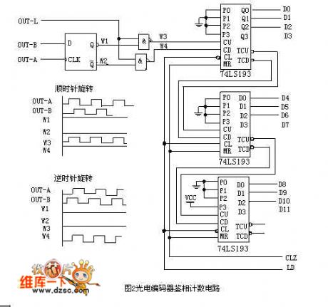
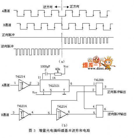
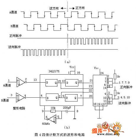
In the angle measurement, displacement measurement, it has a strong anti-interference ability and a stable and reliable output pulse signal. And after the pulse signal obtained by counting, the number of signals can be measured. Therefore, when we develope driving simulator for the steering wheel rotation angle measurement, we use EPC-755A optical encoder as the sensor. The outgoing circuit selects an open-collector. The output resolution selects 360 pulse / cycle. It needs the encoder output signal phase before counting.
D flip-flop outputing Q (waveform W1) is high, Q (waveform W2) is low. It is sent to counter 74LS193 bi-directional, then thepulse is input plus CU to plus count; At this point, the following NAND gate is closed, the output is high (waveform W4).
(View)
View full Circuit Diagram | Comments | Reading(2780)
The logic circuit diagram composed of photocoupler
Published:2011/9/15 1:21:00 Author:Rebekka | Keyword: photocoupler , logic circuit
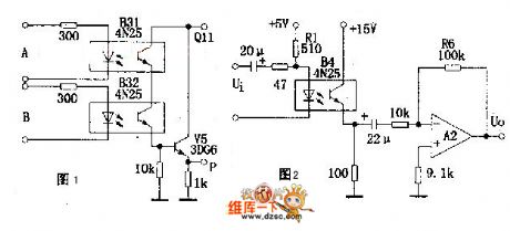
Figure 1 is AND gate logic circuit. Its logic expression is P=A, Figure B has 2 photodiodes in series. When input logic level A=1, B=1, output P=1. In a similar way, itcan form Or gate , NAND gate , NOR gate and some other logic circuits.
As shown in figure 2, it is a typical AC coupling amplifier circuit, which is suitable for selecting lighting loop SFCL Rl to make B4's current transmission be a constant and protect the linear amplifier effect of the circuit. (View)
View full Circuit Diagram | Comments | Reading(1787)
The circuit of logic probe with memories
Published:2011/9/15 1:17:00 Author:Rebekka | Keyword: logic probe with memories
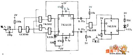
The circuit can be used for camera jitter detection. It is suitable for ±15V input signal. When the probe inputs 1, the negative trigger terminal of dual monostable circuit 74LS123 is in low level, light LED1 is lit, when the input falls down, 9 will be triggered and 5 has a transition. LED1 shows 20ms dark time. When the input is 0, LED 2 is dark, but the positive jump will make LED1 show 20ms light schedule. The 13 and 5 of 74LS123 have the function of memory. (View)
View full Circuit Diagram | Comments | Reading(2085)
Optical coupling circuit for bistable output
Published:2011/9/26 1:41:00 Author:Rebekka | Keyword: bistable output , optical coupling circuit

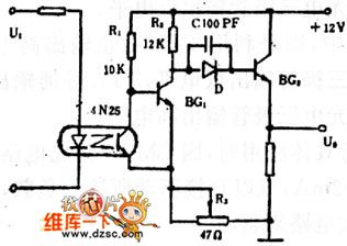
Figure (a) shows the circuit of the control of bistable optical coupler output switch circuit, which is characterized by coupling the optical switch connected to the two emitter back on the road. It can effectively solve the isolate the problem between the output and load.
Graph (b) shows the circuit for the optical coupling switch Schmitt circuit. When the input voltage U1 is low, the optical transistor C and e are in high resistance, BG1 will be conducted, BG2 stops, the output voltage U0 is low; when the amplitude of the input voltage U1 is greater than amplitude discrimination value, the optical transistor c and e are in low resistance, the BG1 stops, BG2 will be conducted, the output U0 is high voltage. You can change the level of amplitude discrimination by adjusting resistor R3.
(View)
View full Circuit Diagram | Comments | Reading(936)
1.5v LCD circuit diagram
Published:2011/9/15 1:51:00 Author:Rebekka | Keyword: 1.5v LCD
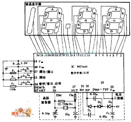
Motorola's MC1440 CMOS integrated circuit has the functions of completion time, display calendar. 32.768KHZ NT cut-type quartz crystal and fine-tuning capacitor can generate time-base signal. The monitor circuit only uses 1.5V AAA battery, and the watch circuit can work more than one year, and accuracy is less than the ± 1min. The voltage tripler composed of MBD101 Schottky diode can switch the 1.5V battery output voltage into 4V for the LCD monitor. (View)
View full Circuit Diagram | Comments | Reading(1981)
Light pen connector circuit diagram
Published:2011/9/15 1:27:00 Author:Rebekka | Keyword: light pen connector
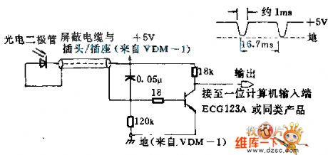
If you put any high-quality photodiodes in a waste barrel and take it to fluorescence-screen display, you can pick up optical signals. If the diode is put into plastic lens, you need to sand Lens side by emery cloth to make the light angle. The set is desgned for matching VDM-1 display terminal. When you move the light pen by the face of the screen, the cathode ray oscilloscope can be used for monitoring the outcoming signal of the circuit. In the dark space of the face of the screen, it produces 5V DC level; in the bright region, the level will fall down. (View)
View full Circuit Diagram | Comments | Reading(1174)
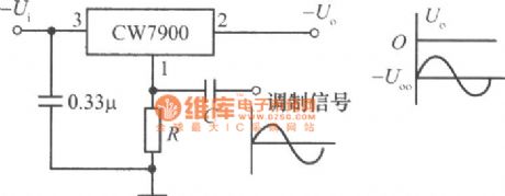
The power modulator circuit made by CW7900
Published:2011/9/26 21:21:00 Author:Rebekka | Keyword: Power modulator
View full Circuit Diagram | Comments | Reading(841)
The fuse fusing instruction circuit diagram
Published:2011/8/3 2:35:00 Author:Ecco | Keyword: fuse fusing instruction
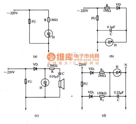
The fuse fusing instruction circuit is shown in Figure 1, and it is very simple. Figure (a) shows the immediate light indicator circuit after fusing; figure (b) shows the instructions circuit, which can flash after fusing; figure (c) shows the circuit, which can issue the sound and light; figure (d) shows the circuit, in which the neon tube issues ligh before fusing and flashes after fusing.
(View)
View full Circuit Diagram | Comments | Reading(845)
TWH8778 power driver switch integrated circuit diagram
Published:2011/8/2 1:20:00 Author:Ecco | Keyword: power , driver , switch , integrated circuit
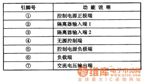
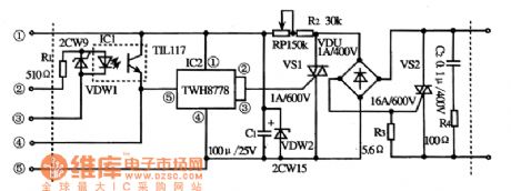
TWH8778 is a power driver switch IC, which is a common component used in many areas of the trigger-driven switch. 1. Features of functionsTWH8778 IC is made by FET and bipolar transistors using hybrid technology, it has the features of low static power consumption and high gain characteristics. The internal circuitincludes short circuit, overvoltage, overheating and other protection circuits, it also can work under poor environment and load conditions, it is small and easy to install. 2. Pin function TWH8778 IC uses single pin package, the pin functions are listed in Table. TWH8778 IC pin function 3. The typical application circuit The factory automatical control switch typical application circuit composed of TWH8778 integrated circuit is shown as the chart. The typical application circuit of TWH8778 integrated circuit
(View)
View full Circuit Diagram | Comments | Reading(1327)
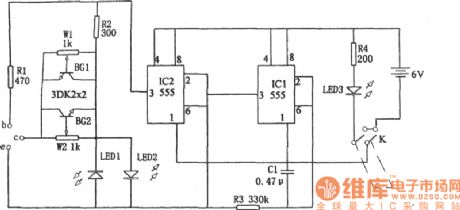
555 transistor quality discriminator circuit diagram
Published:2011/8/4 5:02:00 Author:Ecco | Keyword: 555, transistor , quality discriminator
View full Circuit Diagram | Comments | Reading(834)
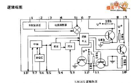
LMl872 logic box circuit
Published:2011/9/25 22:55:00 Author:Ecco | Keyword: logic box
View full Circuit Diagram | Comments | Reading(646)
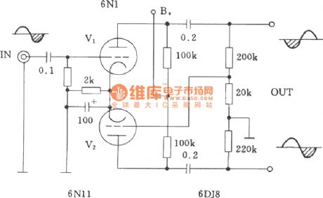
Tube cathode-coupled inverter circuit
Published:2011/9/25 22:11:00 Author:Ecco | Keyword: Tube cathode-coupled inverter
View full Circuit Diagram | Comments | Reading(704)
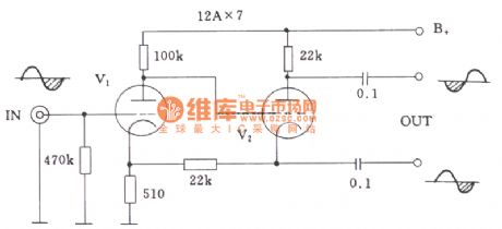
Tube partial-pressure inverter circuit
Published:2011/9/25 22:12:00 Author:Ecco | Keyword: Tube partial-pressure inverter
View full Circuit Diagram | Comments | Reading(842)
Tube differential inverter circuit
Published:2011/9/25 22:14:00 Author:Ecco | Keyword: Tube differential inverter
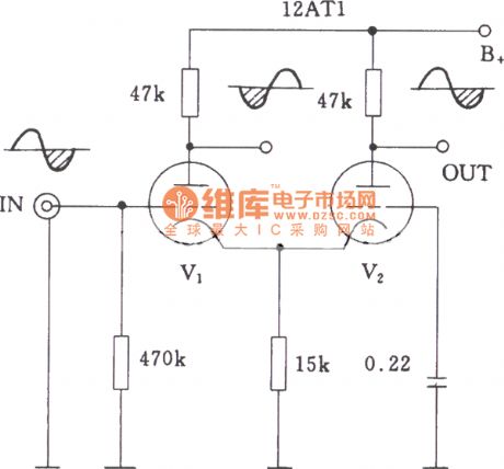
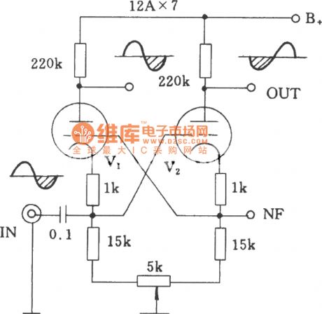
Tube differential common-gate inverter circuit:
(View)
View full Circuit Diagram | Comments | Reading(1450)
| Pages:107/471 At 20101102103104105106107108109110111112113114115116117118119120Under 20 |
Circuit Categories
power supply circuit
Amplifier Circuit
Basic Circuit
LED and Light Circuit
Sensor Circuit
Signal Processing
Electrical Equipment Circuit
Control Circuit
Remote Control Circuit
A/D-D/A Converter Circuit
Audio Circuit
Measuring and Test Circuit
Communication Circuit
Computer-Related Circuit
555 Circuit
Automotive Circuit
Repairing Circuit