
Index 117
Zhonghua saloon car ABS circuit (3)
Published:2011/9/4 20:43:00 Author:TaoXi | Keyword: ZhongHua, saloon car, ABS
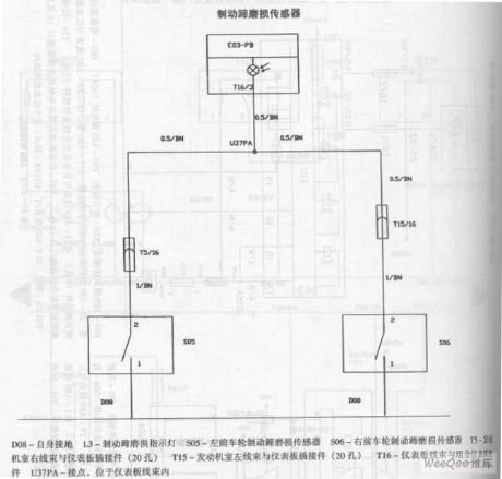
The ZhongHua saloon car ABS circuit (3)
D08-grounding L3-brake shoe attrition indicator light S05-Left front wheel brake shoe attrition sensor S06-Right front wheel brake shoe attrition sensor T5-Engine room right wiring harness and dashboard connector T15-Engine room left wiring harness and dashboard connector T16-dashboard wiring harness and integrated instrument panel plug-in connector U37PA-connection point, in the dashboard wiring harness (View)
View full Circuit Diagram | Comments | Reading(854)
Diamond-shaped Bridge Analog Switched Circuit
Published:2011/9/3 10:27:00 Author:Zoey | Keyword: Diamond-shaped, Bridge, Analog Switched Circuit
Following picture refers to the diamond-shaped bridge analog switched circuit, this circuit can turn on and turn off analog signals that have a peak of 3v in 3ns. Symmetrical drive circuits can switch on and switch off quadruple transistor diamond-shaped bridge circuits with a clock frequency of 20MHz. Typical ascending time of 1-v direct current analog input signal is 1.5ns, descending time is 2ns. This circuit can meet the sampling-maintenance requirements of multiplex converter and pulse code modern remote-testing modulator that has a frequency of 100Mb/s. (View)
View full Circuit Diagram | Comments | Reading(945)
Logic-control Analog Switched Circuit
Published:2011/9/3 10:30:00 Author:Zoey | Keyword: Logic-control, Analog Switched Circuit
The logic-control analog switched circuit has been shown in the following picture. This switched circuit adopts 2N4860 junction field effect transistor, so its conduction resistance is only 20Ωand the pinchoff drain current is small. Operational amplifier LM102 constitutes a voltage follower and plays an important role in buffering. S67800 voltage converter can drive the switched circuit if controlled by DTL and TIL level. (View)
View full Circuit Diagram | Comments | Reading(868)
Servo Circuit
Published:2011/9/3 10:31:00 Author:Zoey | Keyword: Servo Circuit
Following picture shows the servo circuit, this switched circuit uses μA795 Analog multiplier and μA741 operational amplifier to produce AC error signals, and then drives the two-phase servo electronic machine, the direct input signal will be added to pin9,and AC signal will be added to pin 4 via R1 and C1, servo position signal will be added to pin 12. The multiplier takes the signal margin of pin 9 and pin 12 and multiply it by signals on pin 4, then input the value to operational amplifier from pin 14. As soon as actions of the servo electronic machine equalize voltage on pin 9 and pin 12, the system will turn to be 0. (View)
View full Circuit Diagram | Comments | Reading(772)
Sine wave output circuit composed of the TL082
Published:2011/8/24 21:30:00 Author:Christina | Keyword: Sine wave, output circuit
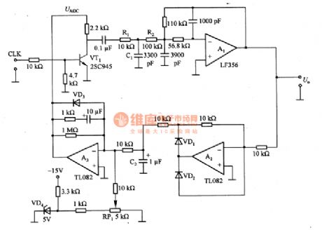
The sine wave output circuit which is composed of the TL082. The CLK is the input clock signal, it has the frequency division effect to the signal which is produced by the crystal oscillator and it changes the signal into the 1 kHZ clock signal. VT1 is the amplitude modulation circuit, we use the 1 kHZ clock signal to control the on/off of the control voltage UAGC to make it produce the square wave, and then we use the low-pass filter to filter out the higher harmonic. The R1 and C1 can be used to set the time constant of the rising edge of the square wave, the c=3~A (c is the cutoff frequency of the wave filter). in order to design the filter accurately, we can set the buffer amplifier A1 to isolate the R1 and R2.
(View)
View full Circuit Diagram | Comments | Reading(2182)
Temperature compensation circuit with the thermistor
Published:2011/8/24 21:30:00 Author:Christina | Keyword: Temperature, compensation, thermistor
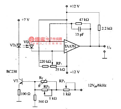
The temperature compensation circuit with the thermistor is as shown in the figure. It is designed as the temperature-compensation circuit of the infrared light-emitting diode VD1, the VD1 can be used as the photodetector of the modulated light, the maximum current is 50mA, the temperature range is 10-55℃. RT can be used as the thermistor with the negative temperature coefficient, and it is connected with the base of VT1 to reduce the self-heating effect of the thermistor. The RP2 and RP3 can be used to adjust the temperature compensation feature. VD2 is the receiver that can amplify the receiving signal through the TAA761.
(View)
View full Circuit Diagram | Comments | Reading(1841)
AN5836 audio preamplifier and control integrated circuit
Published:2011/9/8 19:58:00 Author:Christina | Keyword: audio preamplifier, control, integrated circuit
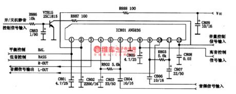
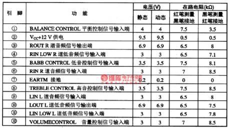
The AN5836 is designed as the audio preamplifier and control integrated circuit that is produced by the Panasonic company, and it can be used in the TV sound system and home theater system.
1.The typical application circuit of the AN5836
The typical application circuit of the AN5836 is as shown in figure 1.
2.The pin functions and data of the AN5836
The AN5836 uses the single row 12-pin package, the pin functions and data are as shown in table 2.
3. The working process of the circuit
The L-IN and R-IN signals are input from the pin-9 and pin-6 of the AN5836 circuit, and the signals are adjusted by the AN5836, then they are output by pin-3 and pin-4. (View)
View full Circuit Diagram | Comments | Reading(4379)
The FM circuit with the transfiguration diode
Published:2011/8/24 21:34:00 Author:Christina | Keyword: FM, transfiguration diode
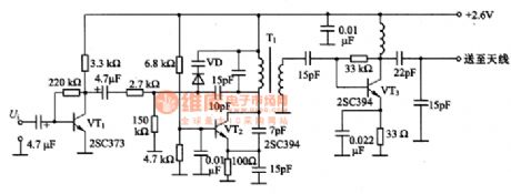
The FM circuit with the transfiguration diode is as shown in the figure. In this circuit, the VT1 changes the signal Ui which is produced by the electret condenser microphone into the operating voltage of the varactor diode VD. The LC oscillator circuit which is composed of the VT2 produces the 80MHz band signal. We can use the varactor diode VD to change the frequency of the resonant circuit, so we do the frequency modulation directly. When the output Vi is 3mV, the modulation frequency is +/-25khz. The VT3 is the high-frequency amplifier, it amplifies the modulated signal to 2.3mV and delivers it to the antenna.
(View)
View full Circuit Diagram | Comments | Reading(854)
The application circuit of the AN6701
Published:2011/8/24 21:34:00 Author:Christina | Keyword: application circuit
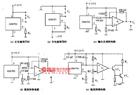
The application circuit of the AN6701 is as shown in the figure. The AN6701 has the features of high sensitivity, the cheaper price, the wide operating temperature range. The main characteristic parameters of it: the temperature range is -10 to +80℃; the sensitivity (Rc=1-100kΩ) is 105-113mV/℃, the nonlinearity is +/-0.5%; the thermal time constant in the still air is 24S, in the wind air is 11S; in the still air, the thermal resistance is 300℃. The output voltage of the sensor (25℃) can be set to 5.0V by the external resistor. The AN6701 is composed of the temperature-sensitive component, the temperature compensation component and the amplifier, it outputs the low impedance. It uses the miniature package to improve the thermal response characteristics.
(View)
View full Circuit Diagram | Comments | Reading(677)
Three-Port CMOS Voltage Regulator Equivalent Circuit
Published:2011/8/23 22:07:00 Author:Robert | Keyword: Three-Port, CMOS, Voltage, Regulator, Equivalent
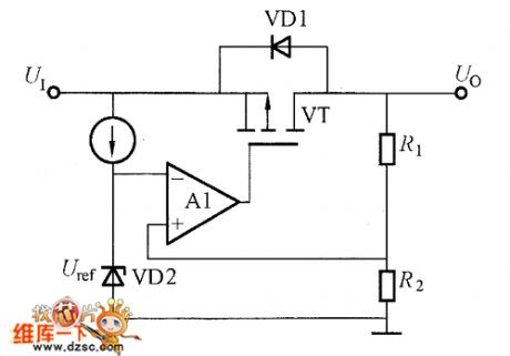
The three-port CMOS voltage regulator equivalent circuit is shown in the picture. Its internal control circuit is made up by the CMOS analog circuit. The output transistor uses the P-channel MOSFET (negatice output voltage uses N-channel MOSFET). The CMOS voltage regulator circuit's structure is simple. Many factories increase its performance by improving its manufacturing process. The CMOS voltage regulator's feature is that there are many products with low output voltage and low loading current, and they have low consumption current. They could be used as the power for charging the battery and local auxiliary power. (View)
View full Circuit Diagram | Comments | Reading(4108)
CF1456 Double-Power General-Type Single-Supply Amplifier Circuit Diagram
Published:2011/9/7 0:47:00 Author:Vicky | Keyword: Double-Power General-Type Single-Supply
CF1456 series operational amplifier is a inner-complementing type high-gaining amplifier. Its input current is relatively low, and power dissipation is very low. There is zero-setting end exteriorly, which has short-circuit protection and over-voltage protection functions. It is available in summing amplifier and intefrator. The analog types or substitutions are CFl556MT、CF1456CT、CF1556MD、CF1456CD、CF1556MJ、CF1456CJ、CF1456CP etc. (View)
View full Circuit Diagram | Comments | Reading(593)
Typical application circuit of intelligent temperature controller MAX6641 based on SMbus
Published:2011/9/8 8:09:00 Author:Felicity | Keyword: intelligent temperature controller
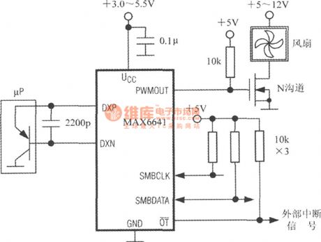
Typical application circuit of MAX6641 is shown in the figure. Using the PWMOUT terminal to drive N-MOSFET and to control the rotational speed of the pan. Remote PN junction temperature sensor can be replaced by the emitter of the triode inside micro processor (μP). Discrete component triode as CMPT3906、T3906、KST3906-TF、SMBT3906 etc. can also be adopted. Under the highest expected temperature and 10μA current the forward voltage drop of the emitter shall above 0.25V ; Under the lowest expected temperature and 100μA current the forward voltage drop of the emitter shall above 0.95V. High power triode shall not be adopted.
(View)
View full Circuit Diagram | Comments | Reading(999)
The constant temperature control circuit composed of 3-line serial spot intelligent temperature sensor DS1620
Published:2011/9/5 22:58:00 Author:qqtang | Keyword: constant temperature control circuit, serial spot, intelligent temperature sensor
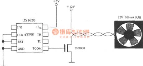
When DS1620 is used to supervise the microprocessor temperature, by opening or closing the fan, the radiation condition can be changed, so the temperature control can be done, see as the figure. Its feature is that TCOM signal controls the fan by 2N7000 MOSFET, when the temperature of the chip surface is higher than tH, the fan is turning on, and the state will last till t
(View)
View full Circuit Diagram | Comments | Reading(1783)
Boiler induced draft fan circuit (2)
Published:2011/9/8 19:56:00 Author:TaoXi | Keyword: Boiler, induced draft fan
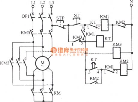
This circuit ensures the Y-△ decompression start has enough delta-time in the switching process. In the KM2 coil control circuit, you can connect two pairs of contact points in series to ensure the circuitto haveenough delta-time in the switching process.
(View)
View full Circuit Diagram | Comments | Reading(1183)
An easy thermostat circuit composed of intelligent temperature sensor LM75 based on I2C Bus
Published:2011/9/8 5:38:00 Author:Felicity | Keyword: thermostat circuit, easy, intelligent temperature sensor
The figure shows an easy thermostat circuit composed of intelligent temperature sensor LM75 based on I2C Bus. LM75 drives the relay coil through 2N3904 transistor according to the test temperature to control the power supply of the thermostat to achieve thermostatic control. (View)
View full Circuit Diagram | Comments | Reading(1627)
Typical application of 7-way intelligent temperature sensor MAX6697
Published:2011/9/8 8:25:00 Author:Felicity | Keyword: 7-way, intelligent temperature sensor
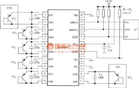
The figure shows the typical application circuit of 7-way intelligent temperature sensor MAX6697. MAX6697 matches 6 temperature measurement transistor (VT1~VT6). The transistors collector is closed to act as diode. VT1,VT6 are used to detect the chip temperature of CPU and GPU.C1~C6 and transistor in parallel can filter out the high frequency disturbance on the signal bus.C7 is power decoupling capacitor. R1~R4 are pull-up resistors.MAX6697 can connect to microprocessor (μP) through SMbus.
(View)
View full Circuit Diagram | Comments | Reading(883)
The low voltage logic circuit composed of intelligent temperature sensor TMP03
Published:2011/9/8 5:07:00 Author:Felicity | Keyword: low voltage logic circuit , intelligent temperature sensor
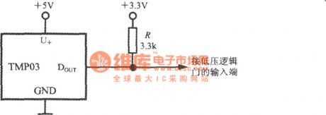
It’s convenient to drive logic gates under low voltage with the collector open. The low voltage logic circuit is shown in the figure. The DOUT terminal of TP03 connects to the +3.3V power through the 3.3kΩ pull-up resistor and the current through R is about 1mA. The output voltage of TMP03 is put on the input terminal of the low voltage logic gate. This circuit adapts +3.3V systems. (View)
View full Circuit Diagram | Comments | Reading(746)
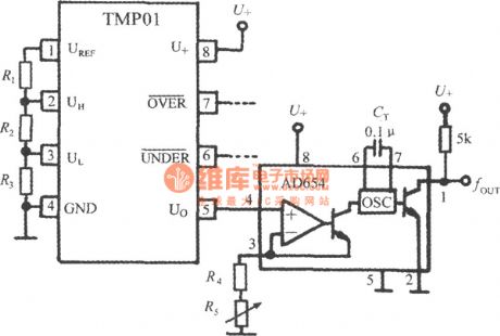
Using twisted pair to transmit temperature signal (low power programmable integrated temperature controller TMP01)
Published:2011/9/8 9:17:00 Author:Felicity | Keyword: twisted pair, temperature signal, low power, programmable integrated temperature controller
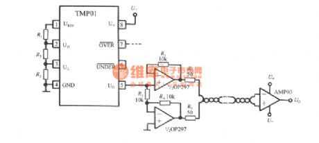
The output signal output by Pin 5 of TMP01 is analog voltage which can be easily disturbed during transmission in industrial sites. Then twisted pair can be adopted as shown in the figure. Firstly using OP297 split Uo into two-way signal and then transmitted through twisted pair and finally received and restored by AMP03. The differential amplifier composed by AMP03 can reduce the noise voltage as 95dB besides amplify the temperature signal. After restoration the lossless voltage signal Uo can be achieved.
(View)
View full Circuit Diagram | Comments | Reading(785)
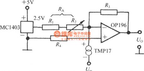
Celsius or Fahrenheit temperature conversion circuit composed of cheap current output integrated temperature sensor TMP17
Published:2011/9/8 8:40:00 Author:Felicity | Keyword: temperature conversion, current output, output integrated temperature sensor
(View)
View full Circuit Diagram | Comments | Reading(984)
Using the PWM3 terminal of the intelligent remote hot fan controller ADT7460 to drive two three-wire fan
Published:2011/9/8 3:25:00 Author:Felicity | Keyword: PWM3 terminal, intelligent remote hot fan controller , three-wire fan
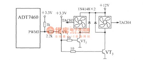
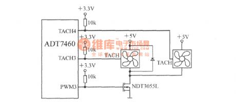
Using transistors:
Using FET:
(View)
View full Circuit Diagram | Comments | Reading(792)
| Pages:117/471 At 20101102103104105106107108109110111112113114115116117118119120Under 20 |
Circuit Categories
power supply circuit
Amplifier Circuit
Basic Circuit
LED and Light Circuit
Sensor Circuit
Signal Processing
Electrical Equipment Circuit
Control Circuit
Remote Control Circuit
A/D-D/A Converter Circuit
Audio Circuit
Measuring and Test Circuit
Communication Circuit
Computer-Related Circuit
555 Circuit
Automotive Circuit
Repairing Circuit