
Index 119
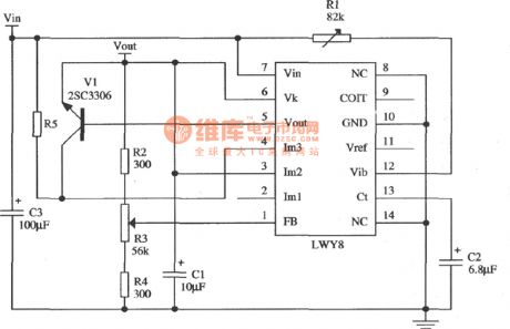
expansive flow application circuit of LWY8 positive integrated voltage stabilizer
Published:2011/8/26 3:33:00 Author:chopper | Keyword: application circuit, positive integrated, voltage stabilizer
View full Circuit Diagram | Comments | Reading(678)
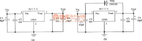
typical application circuit of CW78L××,W78M××,W78H××
Published:2011/8/26 3:30:00 Author:chopper | Keyword: typical, application circuit
View full Circuit Diagram | Comments | Reading(544)
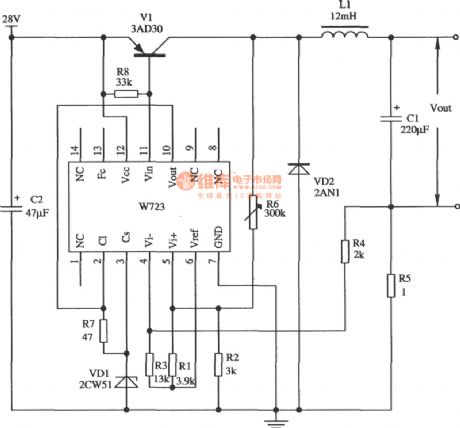
application circuit of switch type constant current source of W723
Published:2011/8/26 3:31:00 Author:chopper | Keyword: application circuit, switch type, constant current source
View full Circuit Diagram | Comments | Reading(632)
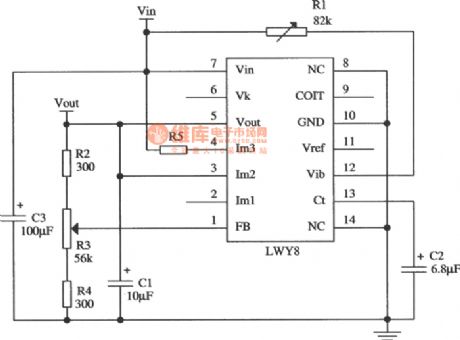
typical application circuit of LWY8 positive integrated voltage stabilizer
Published:2011/8/26 3:34:00 Author:chopper | Keyword: typical, application circuit, positive integrated, voltage stabilizer
View full Circuit Diagram | Comments | Reading(623)
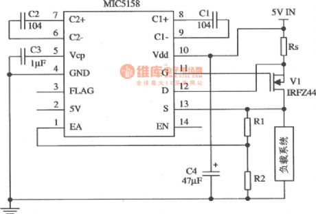
MIC5158 constant current source circuit
Published:2011/8/26 3:35:00 Author:chopper | Keyword: constant current source
View full Circuit Diagram | Comments | Reading(718)
application circuit of light-sensitive control switch of Darlington phototransistor
Published:2011/8/14 1:01:00 Author:chopper | Keyword: application circuit, light-sensitive switch, Darlington, phototransistor
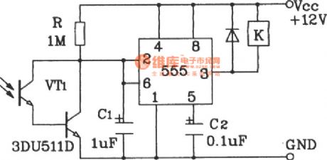
The application circuit of light-sensitive control switch of Darlington phototransistor adopts Darlington phototransistor as the ense organ,so it is sensitive for low-light and it is suitable for the detection of the reflected light signals. (View)
View full Circuit Diagram | Comments | Reading(2241)
application circuit of light triggered switch of Darlington phototransistor
Published:2011/8/14 0:56:00 Author:chopper | Keyword: application circuit, light triggered, switch, Darlington, phototransistor
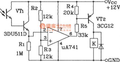
The application circuit of light triggered switch of Darlington phototransistor adopts the sub-type Darlington phototransistor and amplifier, so the weak light can flip the circuit.When the R1 and photodiode are reversed, or the in-phase and reversal phase input ends of the op-amp are reversed,the circuit can be modifiedas the darkness-triggered switch. (View)
View full Circuit Diagram | Comments | Reading(1468)
smart humidity gauge constituted by the humidity sensor and the microprocessor circuit
Published:2011/8/31 1:52:00 Author:John | Keyword: smart humidity gauge, humidity sensor, microprocessor
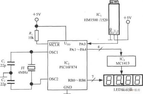
PIC16F874 has a wide range of supply voltage (+2.5 ~ +5 V), which is suitable for low voltage power supply. The quiescent current is less than 2mA. The RA port (RA0 ~ RA7) is the I / O interface. And the PA0 (also known as AIN0) port line is used to receive the voltage signal generated by the humidity sensor. Output bit PA1 ~ PA4 scans signal and receives inverting-phase drive signal through MC1413. Section between RB0 and RB6 of the RB port outputs 7-segment signal. And then the corresponding pen electrodes of LED display is within a ~ g. PIC16F874 also features of power-down protection. And MCLR reset the latch for the power-down side.
(View)
View full Circuit Diagram | Comments | Reading(1138)
The connector circuit with 2 lines of SI intelligent temperature sensor TCN75 and 89C51
Published:2011/8/23 22:41:00 Author:qqtang | Keyword: temperature sensor, connector circuit
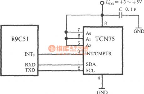
The connector circuit of TCN and 89C51 is shown in the circuit. All the address input terminals A2~A0 of TCN75 are connected with the high LEV UDD, the address code is set to be 111. 89C51 fulfills the selective function with the software. The 89C51 serial data collecting terminal (RXD) and the serial data emitter(TXD) are linked to SDA and SCL of TCN75. The halt/compare signal of TCN75 is linked to the halt terminal INT0 of 89C51.
(View)
View full Circuit Diagram | Comments | Reading(648)
The long-distance temperature test circuit composed of intelligent warm air fan controller ADT7460
Published:2011/8/23 22:41:00 Author:qqtang | Keyword: temperature test, warm air, fan controller
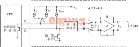
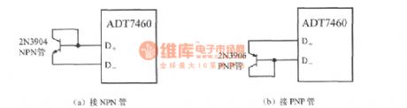
ADT7460 is coupled with 2 long-distance temperature sensors consisting of transistors, it measures distance temperature by using the feature that the transistor emitting knot voltage (UBE) is in forward proportion with temperature. The circuit is shown in the figure. In the figure, the CPU itself is taking a temperature test transistor with it, which is equal to a PNP transistor of 2N3906 type. If a separated transistor is used, the collecting electrode can not connect with the earth, but link with the base electrode as the diode. When using NPN transistor, we should connect the base electrode with terminal D+ and emitter with terminal D.
(View)
View full Circuit Diagram | Comments | Reading(664)
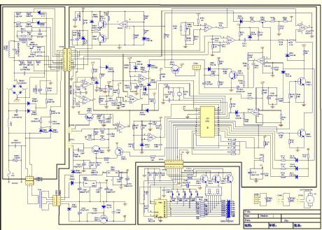
The electromagnetic oven circuit
Published:2011/9/2 3:04:00 Author:Christina | Keyword: electromagnetic oven
View full Circuit Diagram | Comments | Reading(2062)
Panasonic RB28CM razor circuit
Published:2011/9/4 22:25:00 Author:TaoXi | Keyword: Panasonic, razor circuit
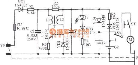
The Panasonic RB28CM razor circuit is as shown in the figure, it uses the low frequency oscillation circuit to produce the oscillation voltage, and this voltage is rectified and filtered by the circuit to charge the batteries.
(View)
View full Circuit Diagram | Comments | Reading(752)
Wanbao BCD148 frost-free refrigerator circuit
Published:2011/9/4 21:26:00 Author:TaoXi | Keyword: Wanbao, frost-free, refrigerator circuit
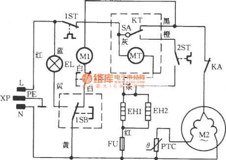
In the figure, the EL is the 220V, 15W light, it is installed in the refrigeration room; 1SB is the refrigeration room door switch, if the door opens, the EL will turn on; 2SB is the freezer door switch, the fan electric motor M1 stops operating when the door opens; KT is the defrost timer; EH1 is the defrost heater, FU is the drainage electric heater.
(View)
View full Circuit Diagram | Comments | Reading(4509)
AC electronic relay circuit
Published:2011/8/29 2:21:00 Author:Jessie | Keyword: AC, electronic relay

As shown in Figure a , the collector is negative, the emitter is positive, and for the PNP tube, the powerwith this polarity is normal operating voltage. As shown in Figure b, the collector is positive, the emitter is negative, andfor NPN Tube, the powerwith this polarityis normal operating voltage.
(View)
View full Circuit Diagram | Comments | Reading(927)
Digital display thermometer circuit
Published:2011/8/26 3:25:00 Author:Jessie | Keyword: Digital display, thermometer
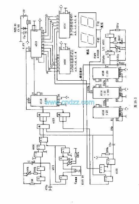
Thecapacitive moisture sensor KHY10 canform the humidity meter whichis displayed by double-digit percentages of LCD display. The pulse width of single state trigger produced by 1kHz quote swings device depends on the sensor elements' capacitance. In zero humidity, single state trigger's pulse width isequal to oscillating wave's half cycle. These two pulses are added to the XOR gate to form the difference pulse signal, and according to the difference between the pulse width, the 200KHz signal is added the AND gate. If there is differential pulse, the output is only pulses.
(View)
View full Circuit Diagram | Comments | Reading(1417)
MPY600 division circuit diagram
Published:2011/8/19 1:43:00 Author:Jessie | Keyword: division
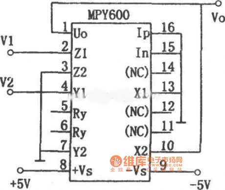
This circuitis composedof multiplier MPY600, inputs are V1 and V2, their input full range is ±2V, its output Vo is: Vo=-2V1/V2. The integrated circuit is as a division, its bandwidth is relevant with V2, the higherV2 is, thebigger bandwidth is. (View)
View full Circuit Diagram | Comments | Reading(658)
XR-2228 division circuit diagram
Published:2011/8/19 1:44:00 Author:Jessie | Keyword: division
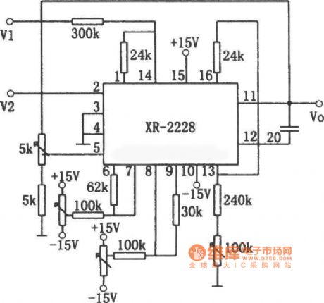
This circuit is composed by monolithic on time-multiplier integrated circuit XR-2228. The relationship of output signal and input signal V1, V2is: Vo=10V1/V2. The input signal V1 can positiveor negative, but V2 mustbe negative. If V2 is positive, the circuit is locked (it will notdamage the manifold). Each potentiometer used to regulate circuit to the best working conditions, and to calibrate the circuit by known reference voltage. (View)
View full Circuit Diagram | Comments | Reading(1127)
LM101, HA2-2520 multiplication circuit diagram
Published:2011/8/19 1:19:00 Author:Jessie | Keyword: multiplication
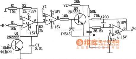
As shown in figure is multiplication circuit, A1 forms voltage controlled current source, A2 forms voltage comparator, A3 forms active low-pass filter. When time constant R1C1 equals to the clock pulse cycle, the relationship between input and output is: Vo=-V1V2/E. If make E=1V, thereare Vo=-V1V2, V1 and V2 required to be positive and limited in 10V, the V1 is slightly below E. Resistors R1, R2 and capacitor C1 require touse thecomponents withgoodtemperature stability. A1is HA2-2520, A2, A3choose LM101A. (View)
View full Circuit Diagram | Comments | Reading(946)
MC1496 multiplication circuit diagram
Published:2011/8/19 1:39:00 Author:Jessie | Keyword: multiplication
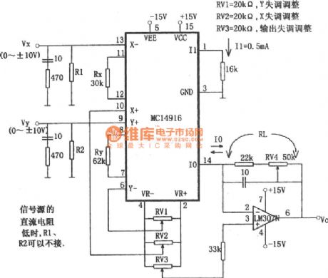
When the circuit selects Rx = 30kΩ, Ry = 62kΩ, I1 = 0.5mA, K = 1 / 10, the output voltage Vo is Vo = VxVy/10 Since the output current Io is inverted by inverting amplifier, so the X-Vx is added to x- end, this is because positive selection of the right side decision; if the right side is selected as negative, the input signal should be added to the X + side. In order to prevent parasitic oscillation, the input end of Vx and Vy is connected 470Ω 10pF network in series. (View)
View full Circuit Diagram | Comments | Reading(1353)
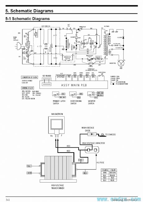
Samsung CE959 microwave circuit
Published:2011/8/30 3:01:00 Author:Christina | Keyword: Samsung, microwave
View full Circuit Diagram | Comments | Reading(1488)
| Pages:119/471 At 20101102103104105106107108109110111112113114115116117118119120Under 20 |
Circuit Categories
power supply circuit
Amplifier Circuit
Basic Circuit
LED and Light Circuit
Sensor Circuit
Signal Processing
Electrical Equipment Circuit
Control Circuit
Remote Control Circuit
A/D-D/A Converter Circuit
Audio Circuit
Measuring and Test Circuit
Communication Circuit
Computer-Related Circuit
555 Circuit
Automotive Circuit
Repairing Circuit