
Index 104
SS0001 internal circuit schematic diagram
Published:2011/9/27 21:13:00 Author:Rebekka | Keyword: internal circuit schematic
SS0001 is a general-purpose sensor control circuit. It not only matches with the output of pyroelectric infrared sensor perfectly, but also matches with a variety of other sensors. (View)
View full Circuit Diagram | Comments | Reading(1172)
LC9301/9305 infrared remote control emmitting and receiving integrated circuit diagram
Published:2011/9/27 22:52:00 Author:Rebekka | Keyword: infrared remote control , emmitting and receiving integrated circuit
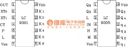
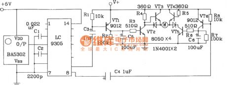
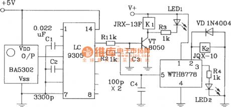
LC9301/9305 IC is an oscillator within encoder and infrared remote control special driver device. It can transimit 4 single codes, each single code will transimit 3 group of coding pulse train signal each time continuously. It improves the reliability of launch information.
The power supply range of LC9301/9305 infrared remote control transmitter/receiver is 4.5~5.5V. The typical value is 5V. External crystal frequency is 4555kHz. Carrier frequency is 38kHz. Their current consumption level is only μA. Transmitter circuit output current is greater than 5mA. It can drive infrared transmitting tube to work directly. The working distance is not less than 8m.
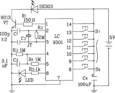
Typical application infrared remote control transmitter circuit composed of LC9301.
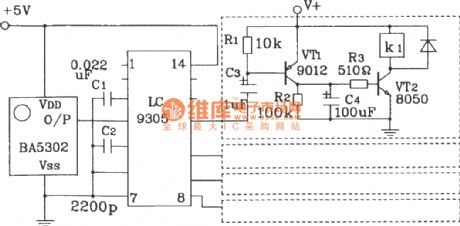
Typical application infrared remote control receiver circuit composed of LC9305.
DC motor forward and reverse remote control receiver circuit composed of LC9305.
Remote relay control bistable trigger circuit composed of LC9305. (View)
View full Circuit Diagram | Comments | Reading(1517)
LC219/220 internal circuitry and pin function circuit diagram
Published:2011/9/27 22:21:00 Author:Rebekka | Keyword: internal circuitry , pin function
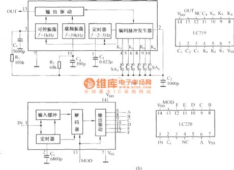
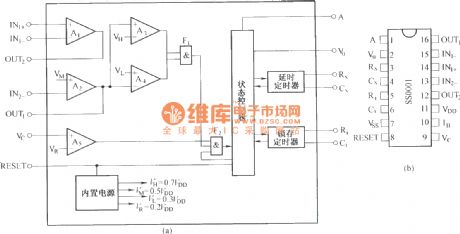
LC219 is a multi-purpose remote coding circuit, not only for the infrared remote control, but also for ultrasonic and radio remote control circuit, and itcan be used to double the wired remote control circuit,it isshown in figure (a). When it is used in radio-controlled, because radio remote control circuit board is specially equipped with the frequency of the oscillator circuit, then the foot can connect ⑩ ground, so that the internal carrier frequency oscillator circuit to stop working. LC220 is the supporting decoder circuit of LC219. It includes the internal buffer circuit, decoder, output circuit and timer, and itisshown in figure (b). (View)
View full Circuit Diagram | Comments | Reading(1161)
MC145026 ~ MC145030 pin function chart
Published:2011/9/27 21:47:00 Author:Rebekka | Keyword: pin function chart
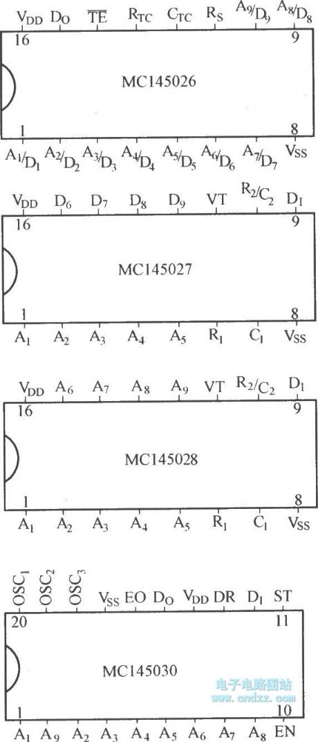
The digital encoding and decoding circuits has different kinds, andMC140000 series is one of them. The series ofcircuit includes MC145026, MC145027, MC145028, MC145029, and MC145030, etc. MC145026 is encoder, MC145027, MC145028 and MC145029 are decoders. MC145030 encoder can be used for the decoder, coding / decoding circuit. (View)
View full Circuit Diagram | Comments | Reading(1161)
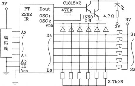
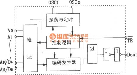
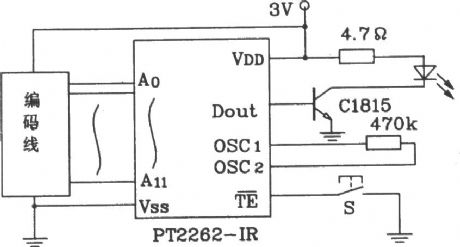
PT2262 IR and PT2272 Infrared remote control transmitter and receiver integrated circuit diagram
Published:2011/9/27 21:43:00 Author:Rebekka | Keyword: integrated circuit, Infrared remote control transmitter and receiver
(View)
View full Circuit Diagram | Comments | Reading(7729)
Infrared remote control household appliances outlet circuit diagram
Published:2011/9/27 1:48:00 Author:Rebekka | Keyword: Infrared remote control, household appliances outlet
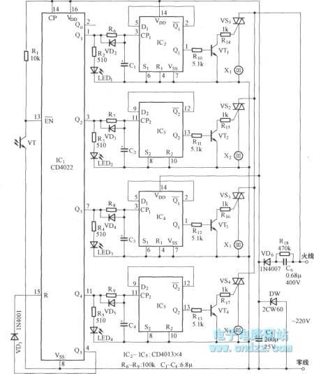
IC1 can use CD4022 or CD4017; IC2 ~ IC5 use dual D flip-flop CD4013; Optical transistor VT1 uses 3DU5; VT2 ~ VT5 use 9013, β> 80; VD2 ~ VD5 select several IN4148; Optional parameters is TRIAC 1A / 400V TRIAC; LED1 ~ LED5 LED are channel indication LED,they can use Φ5mm red LED.
(View)
View full Circuit Diagram | Comments | Reading(1888)
Infrared remote control music outlet circuit 3
Published:2011/9/27 1:47:00 Author:Rebekka | Keyword: Infrared remote control, music outlet
Infrared transmitter circuit.
Infrared receiver and control circuit.
It includes the infrared remote control transmitter and infrared receiver, decoder, relay control circuits and music circuit. Infrared pulse transmitter circuit is composed of 25kHz pulse oscillation circuit and the infrared transmitter driver circuit. The 25kHz pulse oscillator is composed of R1, R2 and F1, F2 which are inside of six NAND gate. (View)
View full Circuit Diagram | Comments | Reading(1130)
Multi-function infrared counter
Published:2011/9/27 1:45:00 Author:Rebekka | Keyword: Multi-function infrared counter
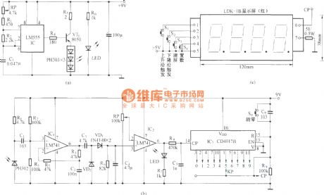
(a) a LM555 circuit diagram composedof the multi-vibrator, and it is usedas the infrared emission control drive pulse generator.
(b) is the infrared receiver that has an infrared receiving tube (PH302) and the two amplifiers.
(c) is the counter. This circuit uses the product four-digit universal counter.
(View)
View full Circuit Diagram | Comments | Reading(1357)
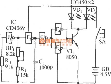
Single infrared light-emitting diode driver circuit diagram
Published:2011/9/27 2:14:00 Author:Rebekka | Keyword: Single, infrared light-emitting diode , driver

View full Circuit Diagram | Comments | Reading(1517)
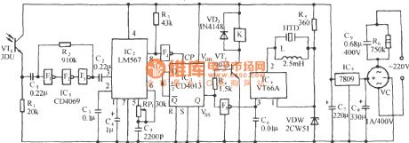
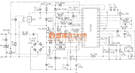
HT7605 SCR Applications circuit diagram
Published:2011/9/27 2:03:00 Author:Rebekka | Keyword: SCR Applications
View full Circuit Diagram | Comments | Reading(1240)
Internal circuit structure of HN911 module
Published:2011/9/27 2:02:00 Author:Rebekka | Keyword: internal circuit structure

HN911 series modules use new technology and new technology. The module circuit is composedof the high sensitivity of pyroelectric infrared sensors, amplifiers, signal processing and output circuit. Its output terminal connects with transistor amplifier or one-shot circuitto drive relay. It connects to the optical coupling circuit to drive the triac. (View)
View full Circuit Diagram | Comments | Reading(758)
BTH801F and BTH801J infrared remote control transmitter and receiver module applications circuit diagram
Published:2011/9/27 2:01:00 Author:Rebekka | Keyword: Infrared remote control, transmitter and receiver
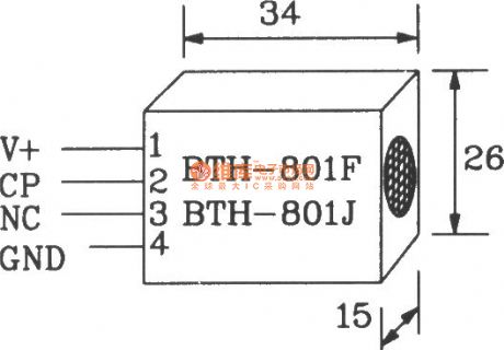
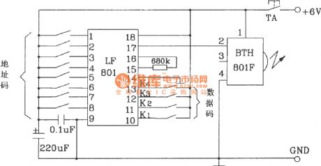
BTH-801F/BTH-801J is the new infrared remote control transmitter / receiver-specific modules. Paired two modules can easily constitute an infrared remote control transmitter / receiver circuit. It is suitable for infrared remote control switches, alarm and many other fields.
BTH-801F/BTH-801J shape pin map.
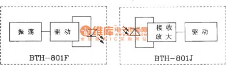
BTH-801F/BTH-801J internal block diagram.
The main electrical parameters of BTH-801F/BTH-801J infrared transmitter / receiver module are as follows: Supply voltage is 4 ~ 8V; Transmitter module operating current is greater than 20mA; Receiver module operating current is less than 3mA; The operation frequency is adjustable within 3060kHz, typical value is 40kHz; Temperature is 18 ~ +60 ℃, storage emperature is 25 ~ +90 ℃; Working distance is 5 ~ lOm.
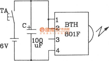
Single infrared remote control transmitter circuit composed of BTH-801F.
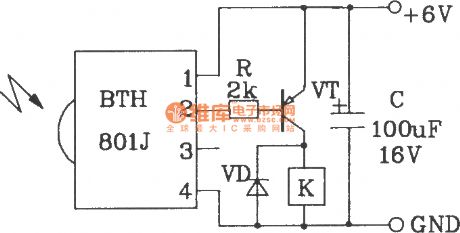
Single infrared remote control receiver circuit composd of BTH-801H.
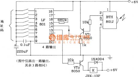
Multi-channel infrared remote control transmitter circuit composed of BTH-801F.
Multi-channel infrared remote control receiver circuit composed ofBTH-801J.
(View)
View full Circuit Diagram | Comments | Reading(2201)
Volt-ampere characteristic curve of photodiode
Published:2011/9/26 22:16:00 Author:Rebekka | Keyword: Volt-ampere characteristic curve , photodiode
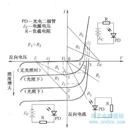
View full Circuit Diagram | Comments | Reading(2294)
The directional property curve of infrared light-emitting diode
Published:2011/9/16 1:17:00 Author:Rebekka | Keyword: infrared light-emitting diode, directional property curve
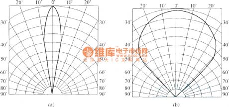
View full Circuit Diagram | Comments | Reading(863)
The volt-ampere characteristic curve of infared light-emitting diode
Published:2011/9/16 1:16:00 Author:Rebekka | Keyword: volt-ampere characteristic curve , infared light-emitting diode
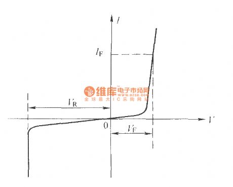
View full Circuit Diagram | Comments | Reading(2222)
HD-03C application circuit diagram
Published:2011/9/27 2:08:00 Author:Rebekka | Keyword: application circuit

HD-03C is a pyroelectric infrared control module. It has a high detection sensitivity, fewer external components. The circuit is simple, easy to use and it can be widely used in automatic switch, automatic alarm control circuit. Figure (a) is the pyroelectric infrared automatic light control circuit composedof HD -03C; Figure (b) is relay output control circuit composed of HD-03C. (View)
View full Circuit Diagram | Comments | Reading(937)
FDD-5/JDD-5 shape and internal circuit diagram
Published:2011/9/27 2:12:00 Author:Rebekka | Keyword: shape , internal circuit
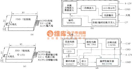
Radio transmitter component FDD-5 and receiver component JDD-5are a pair of FM radio transmitter / receiver modules. The circuit can send either digitally encoded signals and it can transmit audio signals. Their appearance are the metal shell shape packaging, appearance and internal principle. (View)
View full Circuit Diagram | Comments | Reading(892)
SCR circuit diagram with replacing by transistor
Published:2011/10/18 3:04:00 Author:Rebekka | Keyword: SCR , transistor
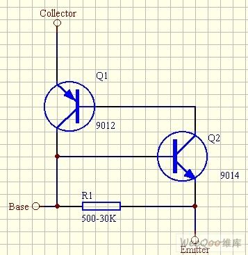
SCR is very general. And it is very easy to buy. It is hard to discrete the use of components chart. This is a self-locking circuit, and perhaps this can be evolved based on some other functional circuits. (View)
View full Circuit Diagram | Comments | Reading(2437)
Voltage follower application example circuit diagram
Published:2011/9/13 2:46:00 Author:Rebekka | Keyword: Voltage follower
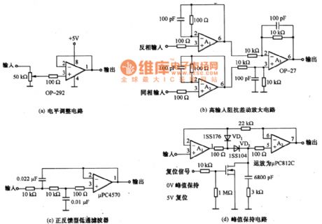
The gain of voltage follower is 0dB. The voltage follower isthe same-phase amplifier circuit. The input impedance in DC range is very high. It is GΩ magnitude. When it has a low utput impedance and ithas μΩ magnitude. It is mainly used as a impedance converter for low-frequency circuit. Figure a, b, c, d are the voltage follower application examples, all these circuits use the features of voltage follower with high input impedance low output impedance. In addition, it is not suitable to use voltage follower. It usually uses inverting amplifier phase amplifier circuit. (View)
View full Circuit Diagram | Comments | Reading(1516)
Emitter follower circuit composed of transistors and op-amp combination
Published:2011/9/13 2:32:00 Author:Rebekka | Keyword: Transistors , op-amp combination, Emitter follower
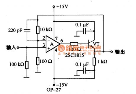
As shown in the diagram, itis the emitter follower composed of transistors and op-amp combinations. For its stability, it needs to access to the bypass capacitor and the series resistor. (View)
View full Circuit Diagram | Comments | Reading(2963)
| Pages:104/471 At 20101102103104105106107108109110111112113114115116117118119120Under 20 |
Circuit Categories
power supply circuit
Amplifier Circuit
Basic Circuit
LED and Light Circuit
Sensor Circuit
Signal Processing
Electrical Equipment Circuit
Control Circuit
Remote Control Circuit
A/D-D/A Converter Circuit
Audio Circuit
Measuring and Test Circuit
Communication Circuit
Computer-Related Circuit
555 Circuit
Automotive Circuit
Repairing Circuit