
Index 113
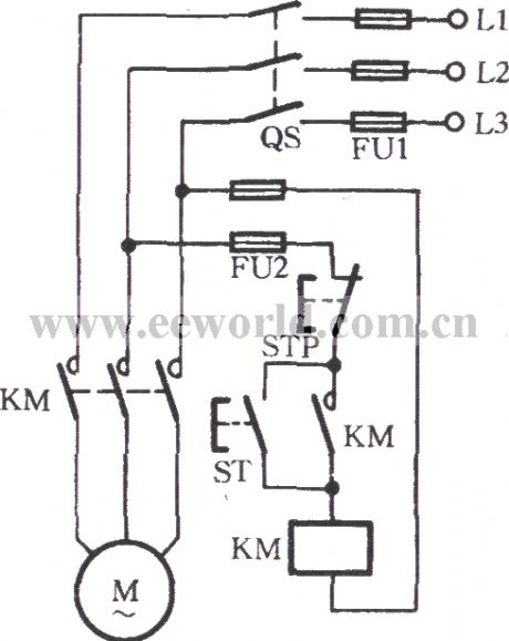
Contactor self-locking operation circuit
Published:2011/9/14 21:56:00 Author:Christina | Keyword: Contactor, self-locking, operation circuit
View full Circuit Diagram | Comments | Reading(1517)
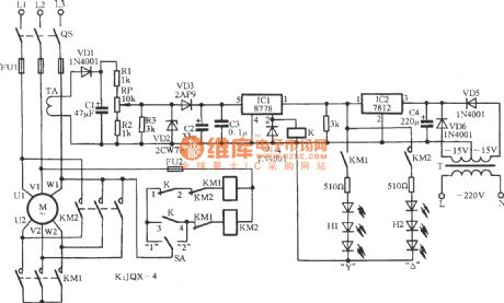
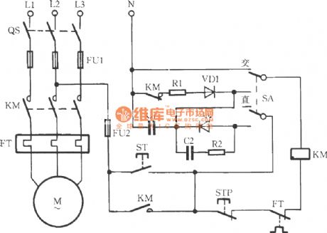
Electricity saving type Y-△ start circuit
Published:2011/9/14 21:55:00 Author:Christina | Keyword: Electricity saving type, Y-△, start circuit
View full Circuit Diagram | Comments | Reading(1230)
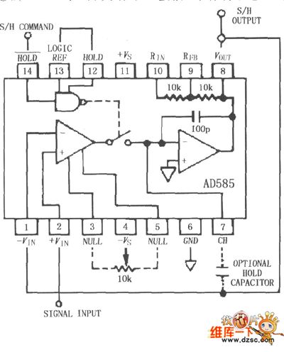
AD585 effective sampling and maintaining circuit with gain = +1
Published:2011/9/14 2:23:00 Author:Ecco | Keyword: effective sampling, maintaining, gain = +1
View full Circuit Diagram | Comments | Reading(714)
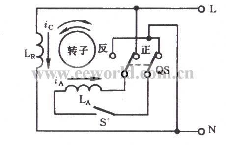
Split-phase start type single-phase electromotor
Published:2011/9/14 21:40:00 Author:Christina | Keyword: Split-phase, start type, single-phase, electromotor
View full Circuit Diagram | Comments | Reading(597)
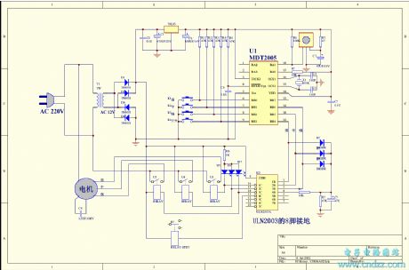
Square model computer automatic electric cooker 3
Published:2011/9/14 21:43:00 Author:Christina | Keyword: Square model, computer, automatic electric cooker
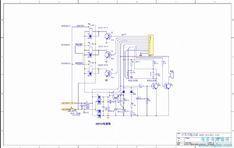
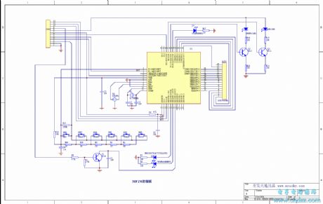
The Square model computer automatic electric cooker has the stereo heating, double sensors, LCD display and backlighting functions.
(View)
View full Circuit Diagram | Comments | Reading(766)
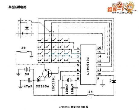
UPDl913C Typical application circuit diagram
Published:2011/9/13 21:26:00 Author:Ecco | Keyword: Typical application
View full Circuit Diagram | Comments | Reading(661)
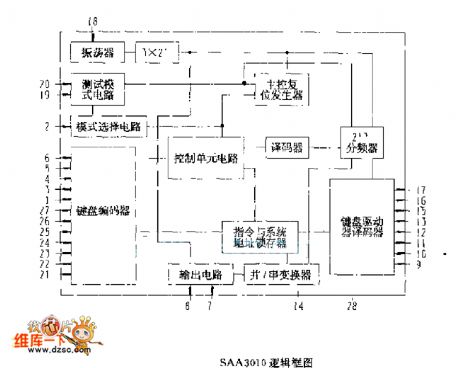
SAA3010 logic box circuit diagram
Published:2011/9/13 21:27:00 Author:Ecco | Keyword: logic box
View full Circuit Diagram | Comments | Reading(728)
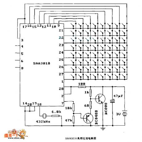
SAA3010 Typical application circuit
Published:2011/9/13 21:24:00 Author:Ecco | Keyword: Typical application
View full Circuit Diagram | Comments | Reading(2202)
HA1377 dual-channel working typical application circuit
Published:2011/9/14 1:59:00 Author:Ecco | Keyword: dual-channel working , typical application

View full Circuit Diagram | Comments | Reading(619)
900MHz radio frequency indicator analysis circuit diagram
Published:2011/9/13 20:39:00 Author:Ecco | Keyword: 900MHz, radio frequency indicator, analysis
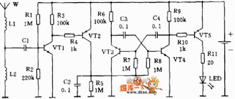
When the phone receives the signal sent by the base station in standby mode, it will send response signal, and cell phone antenna also has a short radio signal. At this point, if there is a tiny sensor next to the phone, it will emit red light, and some sensor will issue music, sound. Anatomy sensor circuit is actually a 900MHz radio frequency indicator. When there is no RF signal near the phone antenna, all will restore quiet. R1's size is relative to the magnification of VT1.
(View)
View full Circuit Diagram | Comments | Reading(1888)
AC contactor power saving noiseless operation circuit
Published:2011/9/14 21:26:00 Author:Christina | Keyword: AC, contactor, power saving, noiseless operation
View full Circuit Diagram | Comments | Reading(1467)
LA7837 Field scanning output IC
Published:2011/9/13 20:18:00 Author:Ecco | Keyword: Field scanning output IC
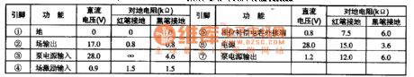
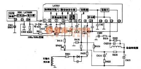
LA7837 field scanning output IC produced by Japan's Sanyo is widely used in domestic and imported color TV. 1. Features and functions LA7837 IC includes field oscillation and sawtooth generator circuit, field excitation and output circuit. The maximum output current is 1.8 AP-P, and the maximum output power is 8W, then the manifold internal block diagram and typical application circuit are shown in Figure 1. 2. pin functions and data LA7837 IC pin functions and data are listed in Table 1-2.
(View)
View full Circuit Diagram | Comments | Reading(6064)
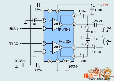
Typical application circuit diagram of BTL connection
Published:2011/9/13 20:43:00 Author:Ecco | Keyword: Typical application, BTL connection
View full Circuit Diagram | Comments | Reading(1032)
Single or dual power quad op-amp with high input impedance circuit
Published:2011/9/14 21:01:00 Author:John | Keyword: Single or dual power quad op-amp
CF14753 is classified into CMOS operational amplifiers. It has four high-performance op-map modules, which is quite similar to MC14753. It is equiped with phase compensation device inside. It is mainly used for a variety of analog computing circuits, AC amplifiers, low frequency waveform generators and active filters and so on. It can also be composed of chopper amplifiers and automatic zero op-amp. Substitutions or direct models are CFl4573, 5G14573, MCl4573, CHl4573 and CAl4573 and so forth.
(View)
View full Circuit Diagram | Comments | Reading(1196)
signal amplitude comparison circuit
Published:2011/9/14 19:49:00 Author:Nancy | Keyword: signal amplitude

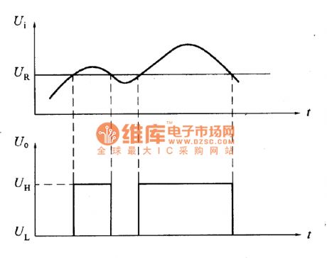
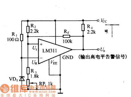
The figure shown is computer power test circuit, which uses LM311 integrated voltage comparator.When the power supply voltage VCC is low, it can output alarm signal, which causes the computer to take immediate processing measure to protect the data. The reference voltage UR in the circuit is decided by the value of voltage-regulator diode VD1, and can choose different voltage values according to the need. The input voltage Ui of the comparator is decided by the voltage division of R2, R3 and RP1, which is proportional to the Vcc supply voltage Vcc. The main function of feedback resistance Rf is to accelerate the overturn of the comparator and reduce the transit time of the overturn.
(View)
View full Circuit Diagram | Comments | Reading(833)
Single-phase motor main auto-winding voltage reducing and speed regulating circuit
Published:2011/9/14 20:36:00 Author:nelly | Keyword: Single-phase, motor, auto-winding, voltage reducing, speed regulating
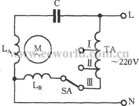
As shown in the picture, the voltage reducing characteristic of the autotransformer can be used to reduce the voltage of main winding LR directly, so that the intention of voltage reduction and speed regulation can be implemented. TA is the autotransformer; I, II, III are the gears. Because the III reduces most of the voltage, the rotation rate will be lowest when the SA reaches III. LA is the assisted winding, and LR is the main winding.
(View)
View full Circuit Diagram | Comments | Reading(1165)
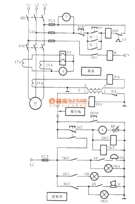
One-wire remote control pump circuit
Published:2011/9/14 20:36:00 Author:nelly | Keyword: One-wire, remote control, pump
View full Circuit Diagram | Comments | Reading(764)
Electric relay open phase protection circuit
Published:2011/9/14 20:36:00 Author:nelly | Keyword: Electric relay, open phase, protection
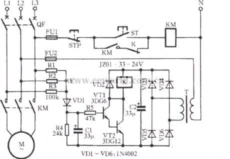
Asshowninthepicture,whenthemotorisrunningnormally,thevoltageofthemiddlepoint”E”isnothighinthethree-phaseYconnectionbalancedcircuit,sotheVD1isnotConducted,andthemultiunittubes(VT1、VT22)arecutoff.TherelayKisinthestateofrelease;afterthefaulthashappened,thepoint“E”increasestowardsthezerolinevoltage.TherectificationoftheVD1makestheemitterofmultiunittubeconduct,Kactuate.Theconstantclosepointopens,andthecontactorKMloseselectricpower.MotorMstopsturningaround. (View)
View full Circuit Diagram | Comments | Reading(1607)
Doppler effect and illumination double-control automatic gate socket outlet circuit RD627
Published:2011/9/14 20:35:00 Author:nelly | Keyword: Doppler effect, illumination, double-control, automatic gate, socket outlet
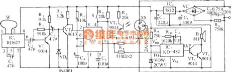
Asshowninthepicture,itiscomposedofDopplereffectsensinghead,lightcontrolswitch,monostabletrigger,SCRcontrolcircuit,musicsoundercircuit,ACvoltagereductionrectifiercircuitandsoon.Whenvehiclesandpeoplearenearthegate,thedoorwillopenautomatically;meanwhile,amelodiousmusicwillbeplayed. (View)
View full Circuit Diagram | Comments | Reading(1337)
Single bond touch sensing key design circuit
Published:2011/9/14 20:35:00 Author:nelly | Keyword: single bond, touch, ensing key, design
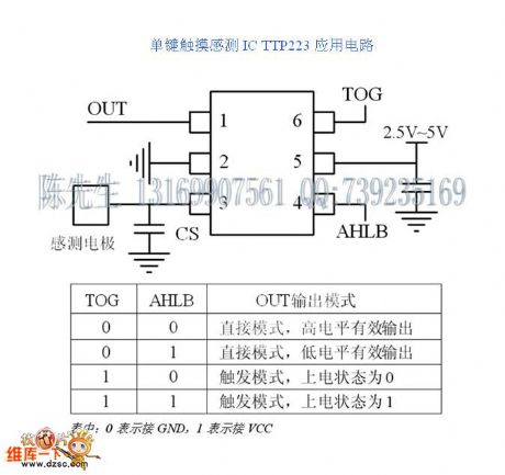
SinglebondtouchsensingchipTTP223canbeappliedfordifferentkindsofeletronic devices. The design issimple,andtheapplicationsareflexible.Thereferencecircuitisintheattachment.
Characterdescription: 2.5V~5Vwideworkingvoltagerange,3uA~5uAsuper-lowworkingcurrent SOT23-6package,smallvolume,convenientdesign ThereisonlyaCScapacityinPeripheralequipment.Thecircuitissimple Thesensingdistanceisover5cm,whichcanbeadjustedbychangingtheCScapacityparameter Variouskindsofoutputmethodscanbechosen ItcanpartlyreplacetheQT100,andthecostislow Ithasthepowerfulanti-jammingperformance,anditwillnotbetriggeredwrongly. (View)
View full Circuit Diagram | Comments | Reading(1583)
| Pages:113/471 At 20101102103104105106107108109110111112113114115116117118119120Under 20 |
Circuit Categories
power supply circuit
Amplifier Circuit
Basic Circuit
LED and Light Circuit
Sensor Circuit
Signal Processing
Electrical Equipment Circuit
Control Circuit
Remote Control Circuit
A/D-D/A Converter Circuit
Audio Circuit
Measuring and Test Circuit
Communication Circuit
Computer-Related Circuit
555 Circuit
Automotive Circuit
Repairing Circuit