
Index 127
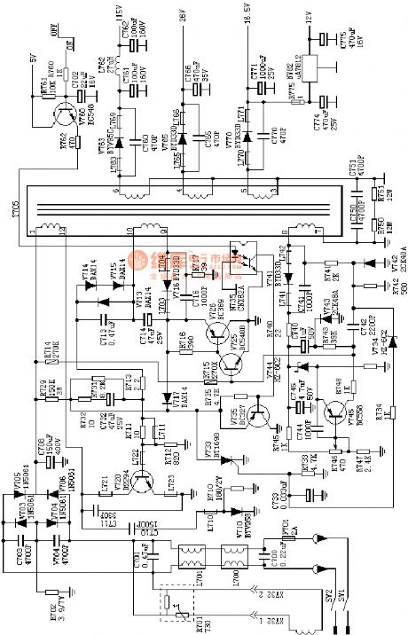
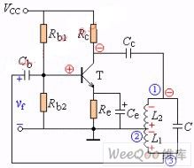
the absolutely useful switch power supply:the TDA two chips system power supply(A4)
Published:2011/8/13 6:49:00 Author:Ariel Wang | Keyword: absolutely useful , switch power supply, two chips system
View full Circuit Diagram | Comments | Reading(933)
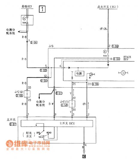
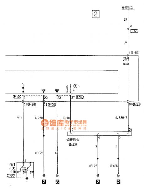
Beijing Cherokee Light Off-road Vehicle Fault Code Circuit
Published:2011/8/3 6:31:00 Author:Michel | Keyword: Beijing Cherokee, Fault Code Circuit
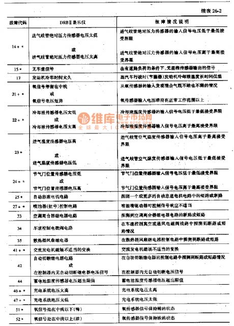
When the Cherokee light sport utility vehicle control circuit has a fault,the CHECKEN-GINE light on the dashboard will spark. The fault code which recorded by the computer will be displayed through manual or DRBII default indicator.In the 5 s,the ignition switch key turns again and again,which makes the ciruit become on-off-on-off-on and the fault code is displayed from the CHECKENGINE indicator.The light sparks for 3s and it is off (to test the bubble) and then the fault code is determined according to the flashing condition of lights and all codes indication are binary.There are 4s time interval among the codes.For example, the light flashes for four times and stops and then flashes for one time,which means that the fault code is 41. (View)
View full Circuit Diagram | Comments | Reading(879)
Record Microcomputer Running Time Counter Circuit of D51602
Published:2011/8/3 6:37:00 Author:Michel | Keyword: Running Time, Counter Circuit
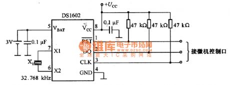
Picture 1 is record microcomputer running time counter circuit of D51602.This circuit is used to record microcomputer control running time.There are two 32-bit counter and the experienced time is counted in seconds.One is continuous work 32-bit counter and it counts the time of the microcomputer.The other is 32-bit counter of AC power supply and it counts the time of the microcomputer.Thus,we can know microcomputer work time and down time.
Picture 1:Record Microcomputer Running Time Counter Circuit of D51602
3 V battery and 32.768 kHz crystals Xl are added to DS1602 and it is connected to the microcomputer via the three thread and the circuit is very simple.32-bit counter can count for 136 years continously.Ac power is off , D51602 current consumption is less than 0.5 μA.And the battery life can be up to 10 years if 50 mAh capacity of the battery can be used.
(View)
View full Circuit Diagram | Comments | Reading(1196)
Measurement Standard Battery Benchmark Voltage Source Circuit of LM199
Published:2011/8/3 6:38:00 Author:Michel | Keyword: Standard Battery, Voltage Source Circuit

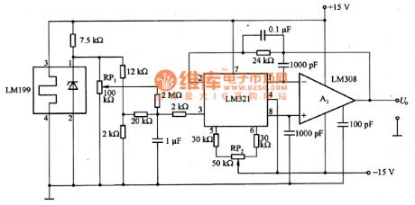
The picture is measurement standard battery benchmark voltage source circuit of LM199 and the benchmark source is 1.01V.The circuit consists of LM321 and LM308 etc. and disorders voltage is below 1μV/℃. The output voltage adjustment RP1 and temperature drift adjustable RP2 need to choose potentiometer with little temperature coefficient ,which does not affect the circuit. (View)
View full Circuit Diagram | Comments | Reading(991)
CXD254Q Digital Servo and Signal Processing Integrated Circuit
Published:2011/8/3 6:39:00 Author:Michel | Keyword: Digital Servo, Signal, Integrated Circuit
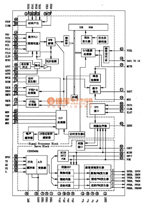
CXD254Q is digital servo and signal processing integrated circuit produced by Sony Company.It is widely used in CD and VCD players.
First,Inside Circuit Block DiagramCXD254Q integrated block circuitis mainly composed of digital servo(D-Servo) and signal processor (DSP).Its inside circuit block diagram is shown as picture 1.
Picture 1:Inside Circuit Block Diagram of CXD254Q Intergrated Block
(View)
View full Circuit Diagram | Comments | Reading(1732)
Thermistors Temperature or Frequency Conversion Circuit
Published:2011/8/1 0:27:00 Author:Michel | Keyword: Temperature, Frequency, Conversion Circuit
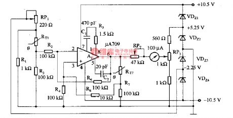
The picutre 3-6 is thermistor temperature or frequency conversion circuit.Because thermistors resistance changes with the temperature in linear way,the change can be used in voltage controlled oscillator.In the circuit,A1-A4 uses current type operational amplifier LM390O,RP1 and RP2 are used to adjust thermistors temperature-resistance properties and the voltage controlled oscillator voltage frequency characteristics.RP3 is used to regulate work range center of voltage controlled oscillator. Adjustment Process:When voltage controlled oscillator output voltage Ui is 7.5V and RP3are regulated,which makes output frequency f。 become 635Hz.lOkΩ calibrating resistance substitutes for thermistor RT and RP2 is regulated to make the output frequency f。 become 635Hz.Then 13·3kΩcalibrating resistance substitutes for thermistor RT again,RP1 is regulated to make the output frequency f。 become 143Hz.Please adjust like this for many times until the satisfying result is obtained. (View)
View full Circuit Diagram | Comments | Reading(957)
SM6781BV Charging Circuit
Published:2011/8/3 7:18:00 Author:Michel | Keyword: Charging Circuit
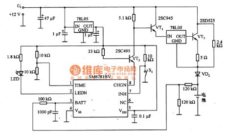
The above charging circuit is composed of SM6781BV.SM6781BV is charging control integrated controller and the tube feet functions are as follows.
Feet 1-Timing Choosing Port The value ofinput port voltage is set as UDD,UDD/2 or 0.
Feet 2(LEDN)-Charging Display LED Driving Output Port It adopts leakage output and the low PWL is output when it is fast charging.When the charging is abnormal and INH port is high PWL,the output pulse is 1HZ.And it is in high impedance condition when the charging is finished.
Feet 3(BATT)—Battery voltage Detection Input End This feet inputs every battery voltage and it adopts resistance to divide the voltage when there are many batteries.
Feet 7 (INH)—Fast Charging Interruptting Input Port It stops fast charging when it is high PWL.It stops charging and begins to charge when it is low PWL. (View)
View full Circuit Diagram | Comments | Reading(1016)
PT2380 Dolby Directional Logic Circuit and Tone Choice Intergrated Circuit
Published:2011/8/3 7:14:00 Author:Michel | Keyword: Dolby Directional, Logic Circuit, Tone Choice, Intergrated Circuit
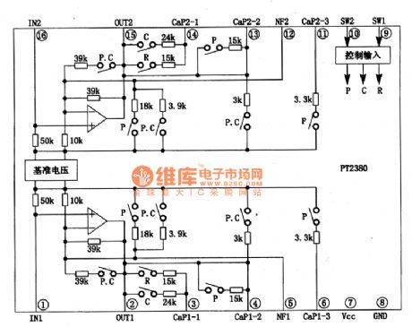
The input voltage of PT2380 is 100mV and work power voltage is 12V.Maximum output voltage undistortion is 3 V, noise level is 0.5-0.6 mV.There are 4 kinds of sound output mode in PT2380,namely,Normal/Flat (Flat), Rock,classical (pop) and POPS (communication).
The four tone modeis controlled by input PWL of SW1 and SW2(⑨ and ⑩ feet).Its inside circuit block diagram of intergrated block is shown as picture 1.
Picture 1:Inside Circuit Block Diagram of PT2380 Intergrated Circuit
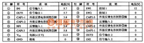
Second,Pins Functions and DataPT2380 IC adopts 16 feet DIP package structure and its pins function and data are shown as table 1.
(View)
View full Circuit Diagram | Comments | Reading(1876)
Battery Charging Circuit for USB
Published:2011/8/3 7:08:00 Author:Michel | Keyword: USB, Battery Charging Circuit
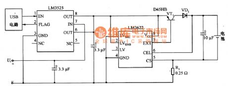
The above picture is battery charging circuit for USB.It is lithium charging circuit with universal serial bus (USB) and the maximum current when it is maximum rating power,5.25V/500mA. In the circuit, LM3622 lithium ion batteries are the controllers.The designing recharging circuit makes USB have the largest power. In normal work situation,the current which is aborbed by the work ability to largest power can not be higher than 5OOmA to satisfy the USB technology index.The biggest charge current is set for 400 mA via limiting resistance R1.And the 100 mA current is provided to charger control circuit etc.During the system starts, LM3525 power switch makes a battery charger and bus remain isolated state.The charging current does not exceed the maximum current provided by the bus. (View)
View full Circuit Diagram | Comments | Reading(1978)
Basic Voltage Regulating Circuit of TL431
Published:2011/8/3 6:45:00 Author:Michel | Keyword: Basic Voltage, Regulating Circuit
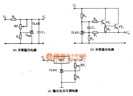
Picture a,b,c are basic voltage regulating circuit of TL431.TL431is composed of reference voltage and error amplifier.And it has the function of variable voltage regulating tube.It can be used as voltage regulating tube ,reference voltage and auxiliary circuit of power supply such as remote control ,overvoltage and multi-output circuits.It can also be used as simple control circuit current-limiting circuit of series regulator and its application is wide.Good voltage UREF temperature characteristic,fast connection and cuttoff,1~100mA absorbing current,low output noise and low output resistance are features of the device.
The picture (a) is simple parallel regulator circuit of TL431 and the output voltage U。=[(1+RRP1/R2)]UREF.In the formula,UREF is the reference voltage of TL431. (View)
View full Circuit Diagram | Comments | Reading(3545)
Micropower Backup Power Supply Circuit of Voltage on Telephone Line
Published:2011/8/3 7:01:00 Author:Michel | Keyword: Telephone Line, Micropower, Backup, Power Supply Circuit
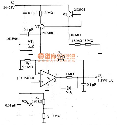
The micropower backup power supply circuit of voltage on telephone is as above.The input voltage Ui of micropower backup power supply absorbs from 24~28V telephone line and the input current is lower than 4μA.The output voltage U。of micropower backup power supply is 3.3V and the current is 1μA.In the circuit,VT1 and VT2 are current source and they provide about 3μA current for A1.A1 are reference voltage circuit and comparator circuit and the maximum static current consumption current is 0.6μA. (View)
View full Circuit Diagram | Comments | Reading(927)
S2560 Microcomputer Dailing Integrated Circuit
Published:2011/8/3 7:16:00 Author:Michel | Keyword: Microcomputer Dailing, Integrated Circuit
S2560 is the microcomputer dialing integrated circuit produced by American Microsoft Company and it is used in communication equipment and dialing integrated circuit.
S2560 integrated circuit can transfer keyboard input transformation into pulse signal output.It can also have storage telecommunication and suspending and redialing functions.It uses feet 18 DIP package structure and its pins functions and data are shown as table 1.
Table 1:S2560 IC Pins Functions and Data (View)
View full Circuit Diagram | Comments | Reading(653)
4-20 mA Input and 5 V Output I/V Switching Circuit of LM324
Published:2011/8/1 22:23:00 Author:Michel | Keyword: 4-20 mA Input, 5 V Output, I/V Switching Circuit
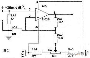
The simple way to solve the above problem is that the buffer processing circuit composed of operational amplifier is installed before singal chip inputs and it is showed as the picture.Increasing this level operation amplifier can make zero processing become easier and it will not cost SCM internal resources.Especially,when single chips uses A/D interface to receive the input of voltage whose zero signal is not zero,which ensures A/D conversion digits capital can be all used in the useful signal.
Take 4 ~ 20 mA for example, the RA0 of picture B is current sampling resistor, and its value is restricted by the sensor power supply voltage, when the current level uses 24 V power supply, RA0 often uses 500 Ω resistance when it is 24V power supply. The voltage is changed into 10V when it's 20mA. (View)
View full Circuit Diagram | Comments | Reading(9140)
OP07 4-20mA Input or 5V Output I/V Converting Circuit
Published:2011/8/1 22:31:00 Author:Michel | Keyword: OP07, 4-20mA Input, 5V Output , I/V Converting Circuit

The circuit is a good recommended line circuit.First of all,it uses high precision voltage regulation circuit composed of TL431 with DIP encapsulation .The dissipation power reaches 1W because TL431 uses DIP encapsulation and it's easy to change dividing resistor by altering power supply voltage.Second,operational amplifiers choose the high precision and low disorders, OP07 and its parameter index is much better than common cheap op-amp.The key is that the output voltage of the op-amp ICC is equal to zero when the input is four mA on zero signal processing.
Work Principle of this Part CircuitThe same phase input port voltage of Op-amp ICD is porvided by negative power which regulated by TIA31 and it divides voltage via R15 and R14. (View)
View full Circuit Diagram | Comments | Reading(4203)
Inductance Three-point LC Oscillator Circuit
Published:2011/8/1 22:24:00 Author:Michel | Keyword: LC Oscillator Circuit
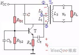
The picture 1 is inductance three-point LC oscillator circuit.Inductance coil L1 and L2 is a coil and 2 point is middle tap.If we suppose that the collector current decreases at a moment and the coil's instantaneous polarity is shown as the picture 1.The triode in the left usescommon-base configuration thus it makes net input of emitter junction decrease and collector current decrease,which is accordwith positive feedback's phase condition.The picture 2is another kind of inductance Bikini LC oscillator circuit.
Pic ture 1:InductanceThree-point Oscillator(CB)
Picture 2:Inductance Three-point LC Oscillator(CE) (View)
View full Circuit Diagram | Comments | Reading(1471)
drive power circuit of LED energy saving lamp
Published:2011/7/27 8:32:00 Author:Fiona | Keyword: energy saving, drive power
LED power supply circuit mostly is composed of switching power supply circuit and feedback circuit,the feedback circuit takes sample from load place,then adjusts the pulse duty cycle or frequency for the switch circuit to achieve the purpose of controlling the switching circuit's output.
(View)
View full Circuit Diagram | Comments | Reading(5388)
The automatic charging, power supply dual-use device circuit (1)
Published:2011/8/1 22:04:00 Author:TaoXi | Keyword: Automatic, charging, power supply, dual-use, device

The automatic charging, power supply dual-use device circuit is as shown in the figure 4-2. IC1 is the three-port voltage stabilizer LM317T, it forms the adjustable voltage stabilization power supply, the output voltage can be adjusted in the range of 1.25V-20V through RP1; IC2 is the CD4060, it is designed as one kind of 14-stage binary addition calculator/oscillator, the timer and pulse generator is composed of this calculator/oscillator and the external components. IC3 is the NE555, it forms the simple automatic charging circuit; IC4 is the sampling controller that is composed of the four-two input NAND gate CD4011 to control the conversion of the charging current.
After the battery is installed, it gives a positive pulse to the pin-12 of IC2 through C6, the IC2 starts to oscillate, the oscillation frequency is about 1.8Hz that is decided by the R6 and R7.
(View)
View full Circuit Diagram | Comments | Reading(664)
The pyroelectric infrared sensing socket analog sound circuit BISS0001
Published:2011/7/26 20:02:00 Author:TaoXi | Keyword: Pyroelectric, infrared sensing socket, analog sound
The circuit is as shown. It is composed of the pyroelectric infrared sensor, the infrared signal processing circuit, the relay control socket circuit, the analog sound circuit and the AC step-down rectifier circuit.etc. When someone walked into the pyroelectric infrared monitoring field, the socket gets the electricity, its electrical equipments start running; meanwhile, the analog sound circuit sends out the voice to remind the equipment master.
(View)
View full Circuit Diagram | Comments | Reading(619)
Southeast Ling Sheng light monitoring buzzer electric system circuit
Published:2011/8/6 21:39:00 Author:leo | Keyword: Light monitoring buzzer, electric system
View full Circuit Diagram | Comments | Reading(885)
The organism moving direction judging circuit composed of heat releasing electric sensors
Published:2011/8/3 22:12:00 Author:Borg | Keyword: direction judging circuit, heat releasing electric sensors
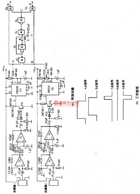
This is the organism moving direction judging circuit composed of heat releasing electric sensors. In the circuit, the heat releasing electric sensors are IRA-F0OlSX (sensor 1 and sensor 2). A1 and A2(A3 and A4) are the 2-stage amplifiers, VTI and NE555(1)(VT2 and NE555(2)) are the waveform processors, which compose the signal processing circuit. Gl一G6 are the direction judging circuitS. NE555(1) and NE555(2) are required to have the unanimous working time, therefore, they need to be adjusted by potentiometer RP1.
The principle of the circuit is shown as follows: if the object moves from sensor 1 to sensor 2, the output pulse of A and B is shown as figure 3-24(b).
(View)
View full Circuit Diagram | Comments | Reading(679)
| Pages:127/471 At 20121122123124125126127128129130131132133134135136137138139140Under 20 |
Circuit Categories
power supply circuit
Amplifier Circuit
Basic Circuit
LED and Light Circuit
Sensor Circuit
Signal Processing
Electrical Equipment Circuit
Control Circuit
Remote Control Circuit
A/D-D/A Converter Circuit
Audio Circuit
Measuring and Test Circuit
Communication Circuit
Computer-Related Circuit
555 Circuit
Automotive Circuit
Repairing Circuit