
Basic Circuit
Index 435
Metal detector 1
Published:2011/4/26 4:38:00 Author:Ecco | Keyword: Metal detector
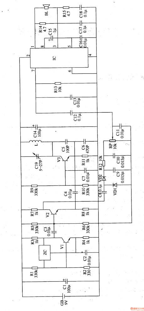
The working principle.The metal detector circuit consists of a fixed frequency oscillator, mixer, detector, detection oscillator and power amplifier circuit, it is shown as Figure 8-67.
Fixed frequency oscillator circuit consists of ceramic filters ZC, transistors Vl and resistors Rl-R4, capacitors C2 and so on. Mixer consists of the mixer tube V2 and capacitor C3, resistors R5-R8. The detector is composed of diodes VDl, VD2, capacitors C8-Cl2 and resistors Rl2, potentiometer RP and other components. Detected oscillator is composed of transistor V3, inductance coil L, capacitors C4-C7, Clg, and resistors R9-Rll. The audio amplifier is composed of power amplifier integrated circuit IC, resistors R13-Rl5, capacitors C13-C18 and speaker BL.
RI-Rl5 use 1/4W carbon film resistors or metal film resistors. Cl and C14, Cl5 select electrolytic capacitors with voltage in 16V; C2-C4, C7-C13 and C16 C18 select monolithic capacitors; C5 and C6 select high-frequency ceramic capacitors; Cl9 uses small polyester film or mica trimmer capacitors. VDl and VD2 select 2AP9 common type germanium diode. Vl-V3 uses S9018 or BM94 silicon NPN transistor. IC uses TDA2822 audio power amplifier integrated circuit.
(View)
View full Circuit Diagram | Comments | Reading(2513)
Metal detector 2
Published:2011/4/26 4:20:00 Author:Ecco | Keyword: Metal detector
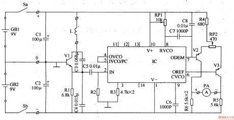
This metal detectors described in the example can be used to detect metal objects with high permeable magnetic substances. The working principle.The metal detector circuit is composed of the power circuit, sine wave oscillator, PLL phase-locked loop circuit and hybrid amplification circuit, it is shown in Figure 8-68.
Power circuit is composed of the battery GBl, GB2, filter capacitor Cl, C2, and the power switch S (Sa, Sb). Sinusoidal oscillator circuit consists of transistors Vl, detecting coil L, capacitor C3-C5 and resistors Rl, R2. PLL circuit is composed of dual time-base integrated circuit and resistors R3, potentiometers RPI, capacitors C6-C8. The hybrid amplification circuit is composed of the transistors V2, V3, resistors R4-R6, potentiometer RP2 and ammeter PA.
Rl-R6 use l/8W or 1/4W carbon film resistors. RPl uses multi-turn precision potentiometer; RP2 uses general lap synthetic membranes potentiometer. Cl and C2 select electrolytic capacitors with voltage in 16V; C3-C5 and C8 select monolithic capacitors; C6 and C7 select high-frequency ceramic capacitors. (View)
View full Circuit Diagram | Comments | Reading(6214)
crystal diode DDZX5V6BTS internal circuit diagram
Published:2011/4/26 10:24:00 Author:Nancy | Keyword: crystal diode

View full Circuit Diagram | Comments | Reading(411)
TCL868-CID03 Communication Single Chip Microcomputer Integrated Circuit
Published:2011/4/26 8:56:00 Author:TaoXi | Keyword: Communication Single Chip, Microcomputer Integrated
The TCL868CDO3 is the 4-bit CMOS microcomputer integrated circuit that belongs to the TCL company, this device can be used in TCL ID phone caller series.
1. Features
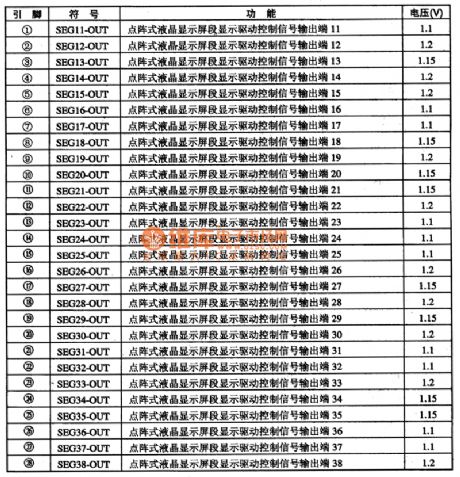
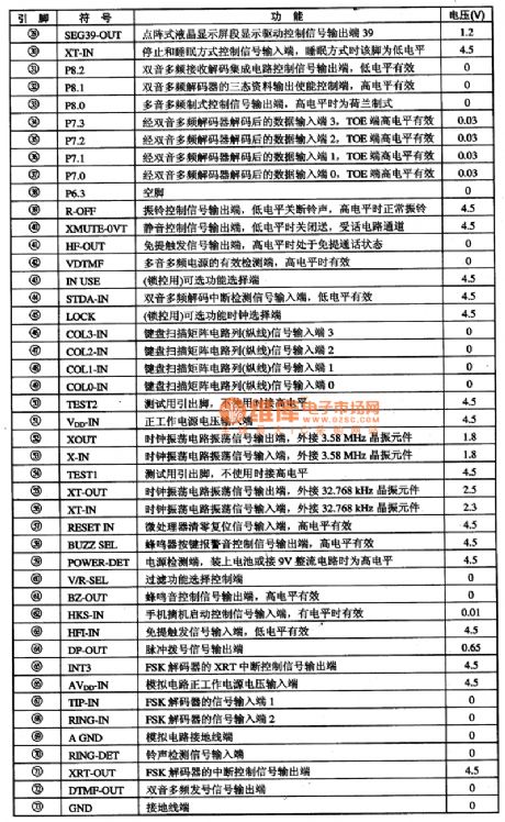
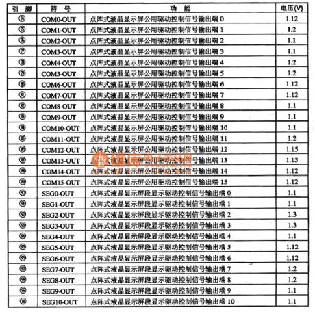
The TCL868CDO3 IC contains the BELL202 or ITU一TV23 standard FSK decoder, the dual audio signal generator, the four-detection platform for low-voltage detection circuit, the LCD driver circuit and the power-saving mode control circuit.etc. It can be used in the call data reception, process and display, and it also has the pulse / DTMF dialing compatible fuction.
2.Pin functions and data
The TCL868CDO3 IC is in the 100-pin softpackage, the IC's pin function and data is as shown in figure 1:
(View)
View full Circuit Diagram | Comments | Reading(632)
Video Switching Circuit
Published:2011/4/26 5:48:00 Author:Robert | Keyword: Video, Switching
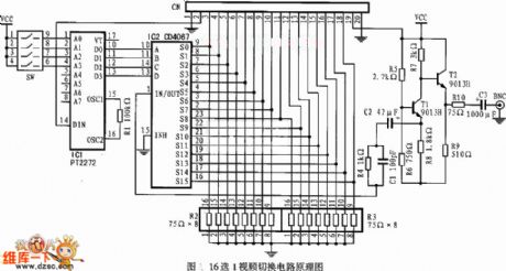
Video Switching Circuit is shown above. It is a16 points 1 video switching circuit. (View)
View full Circuit Diagram | Comments | Reading(813)
XTR101 ELectrlcal Bridge InPut, Voltage Excitation Circuit
Published:2011/4/26 8:39:00 Author:Robert | Keyword: ELectrical Bridge InPut, Voltage Excitation
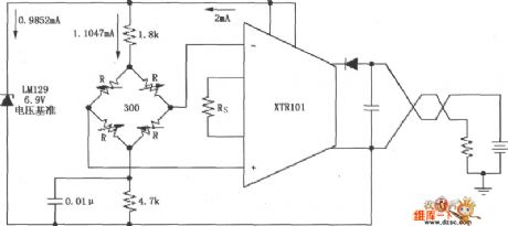
As shown, this circuit uses the voltage regulator tube LM129 to generate a 6.9V voltage reference, andthe 6.9V voltage reference provides 1.0147mA current to the electrical bridge. The electrical bridge could be variable resistance bridge type sensors like the pressure sensor etc.
(View)
View full Circuit Diagram | Comments | Reading(810)
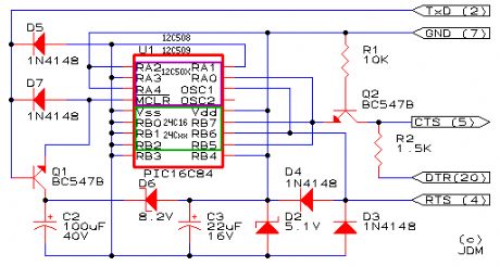
Self-made PIC microcontroller programmer circuit
Published:2011/4/26 3:54:00 Author:Ecco | Keyword: Self-made , PIC , microcontroller , programmer
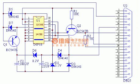
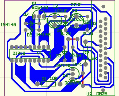
View full Circuit Diagram | Comments | Reading(3815)
crystal diode DDZX5V1BTS internal circuit diagram
Published:2011/4/26 10:28:00 Author:Nancy | Keyword: crystal diode

View full Circuit Diagram | Comments | Reading(492)
crystal diode DDZX22DTS、DDZX24CTS、DDZX43TS internal circuit diagram
Published:2011/4/26 10:32:00 Author:Nancy | Keyword: crystal diode
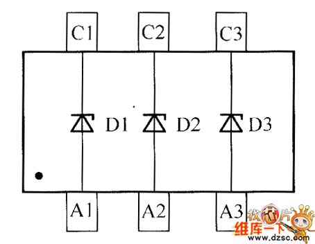
View full Circuit Diagram | Comments | Reading(368)
crystal diode DDZX16CTS、DDZX18CTS、DDZX20DTS internal circuit diagram
Published:2011/4/26 10:34:00 Author:Nancy | Keyword: crystal diode

View full Circuit Diagram | Comments | Reading(417)
crystal diode DDZX13BTS、DDZX14TS、DDZX15TS internal circuit diagram
Published:2011/4/26 10:41:00 Author:Nancy | Keyword: crystal diode

View full Circuit Diagram | Comments | Reading(506)
74 series digital circuit 74LS280 74S280 and other 9 bits odd even generator/validator
Published:2011/4/26 4:32:00 Author:May | Keyword: digital, 9 bits, odd even generator, validator
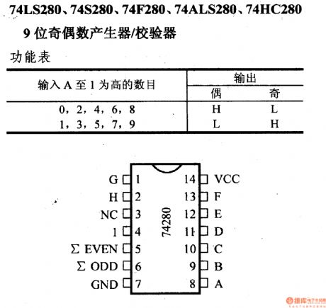
View full Circuit Diagram | Comments | Reading(927)
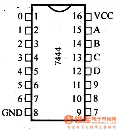
74 series digital circuit 74LS445 BCD decimal decoder/driver (OC)
Published:2011/4/26 3:57:00 Author:May | Keyword: digital, BCD, decimal decoder, driver, OC

74 series digital circuit 74LS445 BCD decimal decoder/driver (OC)
74LS145's low voltage type, withstand voltage is 7V; absorption current is 80mA.; typical power consumption is 35mW; Pin diagram and function table is same to 74LS145. (View)
View full Circuit Diagram | Comments | Reading(2587)
74 series digital circuit 74LS448 four three bus receiver (OC)
Published:2011/4/26 3:59:00 Author:May | Keyword: digital, four three bus receiver, OC
Its pin diagram and function table is same as 74LS440. (View)
View full Circuit Diagram | Comments | Reading(798)
74 series digital circuit 74490 74LS490 etc dual four bit decade counter
Published:2011/4/26 4:07:00 Author:May | Keyword: digital, dual four bit, decade counter
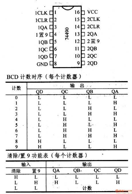
74490, 74LS490, 74HC490 dual four bit decade counter
It is the dual type of 7490A and 74LS90 normal counter. The highest counter frequency is 35MHz. It is buffer output. (View)
View full Circuit Diagram | Comments | Reading(2826)
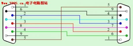
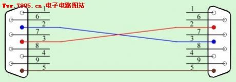
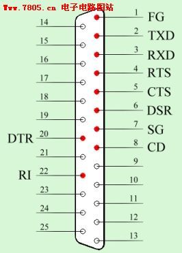
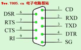
RS232C Pin with the diagonal connections
Published:2011/4/26 3:36:00 Author:Ecco | Keyword: Pin , diagonal , connections

View full Circuit Diagram | Comments | Reading(624)
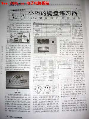
Compact keyboard trainer-the application example of PS / 2 keyboard interface circuit
Published:2011/4/26 3:33:00 Author:Ecco | Keyword: Compact, keyboard trainer, application example , PS / 2, keyboard interface
View full Circuit Diagram | Comments | Reading(529)
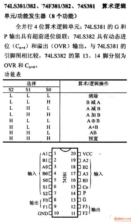
74 series digital circuit 74LS381/382 arithmetic logic unit/association energy generator (eight functions)
Published:2011/4/26 1:57:00 Author:May | Keyword: digital, arithmetic logic unit, association energy generator, eight functions
View full Circuit Diagram | Comments | Reading(1211)
Using LB1413 as electronic thermometer circuit diagram
Published:2011/4/26 3:13:00 Author:Rebekka | Keyword: electronic thermometer

Using LB1413 as electronic thermometer circuit diagram is shown as above. (View)
View full Circuit Diagram | Comments | Reading(1999)
Mileage/N consumption counting circuit
Published:2011/4/25 21:30:00 Author:Nicole | Keyword: mileage
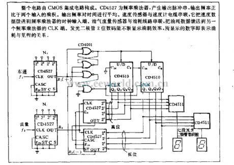
The circuit is composed of CMOS IC. CD4527 is frequency multiplicator, it produces output pulse series, the output frequency is in direct proportion to the product of two inputs. The time is shared by the output frequency. The speed sensor is series with speed indicator cable, it feeds speed data to the clock input terminal of frequency multiplicator. transducer of oil gas flow is series with gasoline consumption line, it feeds gasoline consumption data to CLK terminal of another frequency multiplicator. LED 2 bit digital codes can display the gasoline consumption constantly, the shown nember represents the relation between gasoline consumption and mileage. (View)
View full Circuit Diagram | Comments | Reading(996)
| Pages:435/471 At 20421422423424425426427428429430431432433434435436437438439440Under 20 |
Circuit Categories
power supply circuit
Amplifier Circuit
Basic Circuit
LED and Light Circuit
Sensor Circuit
Signal Processing
Electrical Equipment Circuit
Control Circuit
Remote Control Circuit
A/D-D/A Converter Circuit
Audio Circuit
Measuring and Test Circuit
Communication Circuit
Computer-Related Circuit
555 Circuit
Automotive Circuit
Repairing Circuit