
Basic Circuit
Index 440
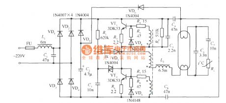
Low cost high power factor electron ballast circuit
Published:2011/4/21 3:42:00 Author:May | Keyword: Low cost, high power factor, electron ballast
View full Circuit Diagram | Comments | Reading(698)
74 series digital circuit 74165 74LS165 and other eight bits shift register (serial-in complementation parallel-out)
Published:2011/4/21 6:04:00 Author:May | Keyword: digital, eight bits, shift register, serial-in complementation parallel-out

View full Circuit Diagram | Comments | Reading(3691)
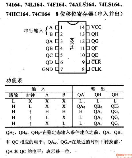
74 series digital circuit 74164 74L164 and other eight bits shift register (serial-in-parallel-out)
Published:2011/4/21 6:02:00 Author:May | Keyword: digital, eight bits, shift register, serial-in-parallel-out
View full Circuit Diagram | Comments | Reading(4564)
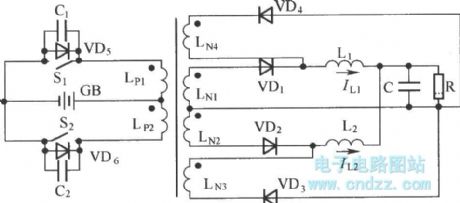
Inductance split type push-pull commutation soft switch circuit
Published:2011/4/14 1:52:00 Author:muriel | Keyword: Inductance split type, push-pull commutation soft switch
View full Circuit Diagram | Comments | Reading(706)
The detection Point of Voltage inverter fault current
Published:2011/4/14 1:52:00 Author:muriel | Keyword: Voltage inverter, fault current, detection Point
View full Circuit Diagram | Comments | Reading(579)
Half four-bit digital voltmeter circuit
Published:2011/4/21 21:12:00 Author:Nicole | Keyword: semi-digital voltmeter
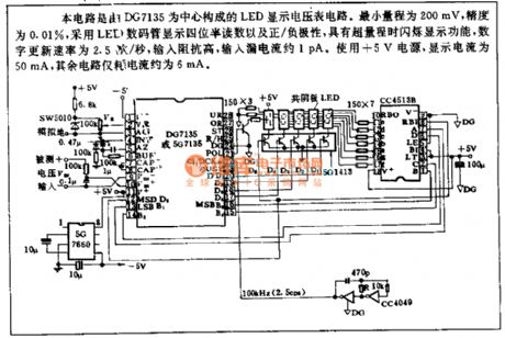
This is a LED display voltmeter circuit composed of DG7135. The minumin range is 200mV, the precision is 0.01%, it adopts LED to display half four-bit reading and positive/negative polarity, it has the flashing function when there is over range, the number update speed is 2.5/s, the input resistance is high, the input leakage current is about 1pA. It uses +5V power supply, the display current is 50mA, the power consumption of other circuit is about 6mA. (View)
View full Circuit Diagram | Comments | Reading(979)
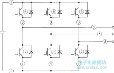
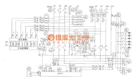
Intermediate frequency power supply major loop with quick short circuit protection
Published:2011/4/20 22:34:00 Author:muriel | Keyword: Intermediate frequency , power supply , major loop , quick short circuit protection
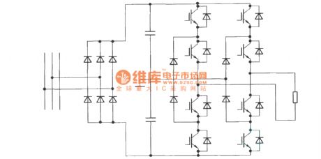
As shown in figure, inverter adopts three-level structure, It not only reduces the device of withstand voltage requirement, but alsois good for decreasing harmonic wave and improving waveform. (View)
View full Circuit Diagram | Comments | Reading(573)
Flagpole pattern display circuit
Published:2011/4/21 8:46:00 Author:Nicole | Keyword: flagpole pattern
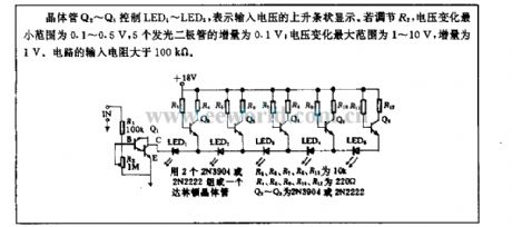
Using transistors Q2~Q6 to control LED1~LED5, the strip shows the rising voltage. To adjust R2, the minimum change range of voltage is 0.1~0.5V, the increment of five LEDS are 0.1V; the maximum change range of voltage is 1~10V, the increment is 1V. The input resistance is more than 100kΩ. (View)
View full Circuit Diagram | Comments | Reading(538)
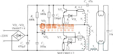
Practical electron ballast circuit
Published:2011/4/21 6:07:00 Author:May | Keyword: electron ballast
View full Circuit Diagram | Comments | Reading(1725)
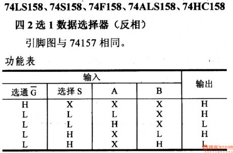
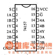
74 series digital circuit 74LS158 74S158 and other 2 choose 1 data selector (opposite phase)
Published:2011/4/21 5:59:00 Author:May | Keyword: digital, 2 choose 1, data selector, opposite phase
View full Circuit Diagram | Comments | Reading(820)
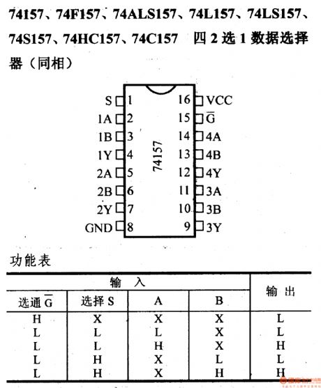
74 series digital circuit 74157 74F157 and other 2 choose 1 data selector (in-phase)
Published:2011/4/21 5:57:00 Author:May | Keyword: digital, 2 choose 1, data selector, in-phase
View full Circuit Diagram | Comments | Reading(4118)
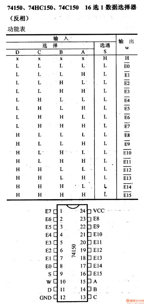
74 series digital circuit 74150 74HC150 and other 16 choose 1 data selector (inverter)
Published:2011/4/21 5:55:00 Author:May | Keyword: digital, 16 choose 1, data selector, inverter
View full Circuit Diagram | Comments | Reading(4078)
DUM23-48/300II AC pdus electrical schematic diagram
Published:2011/4/14 1:31:00 Author:muriel | Keyword: AC , pdus electrical , schematic diagram
As shown in the figure :OBO V20Care Lightning protection modules. The maximum current of lighting damage is 40kA. KM is contactor. FU is fuse. HL is signal lamp. (View)
View full Circuit Diagram | Comments | Reading(1746)
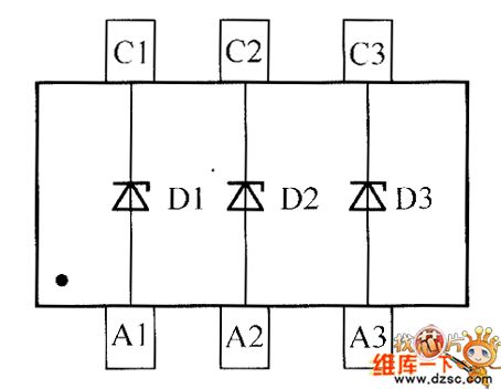
crystal diode DDZX5V2BTS internal circuit diagram
Published:2011/4/21 9:27:00 Author: | Keyword: crystal diode
View full Circuit Diagram | Comments | Reading(424)
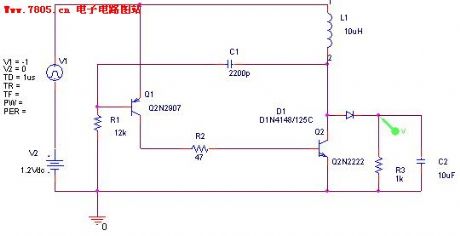
Simple and practical boosted circuit
Published:2011/4/20 20:58:00 Author:May | Keyword: Simple and practical, boosted
View full Circuit Diagram | Comments | Reading(497)
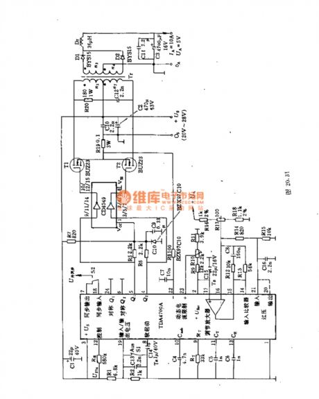
50W DC voltage converter using SIPMOS power transistor and integrated circuit
Published:2011/4/20 21:22:00 Author:May | Keyword: 50W, DC voltage converter, SIPMOS power transistor, integrated
This circuit adopts push pull type DC converter of integrated circuit TDA4700. Its input voltage is 20~28V. Its output voltage is 5V. The maximum load current is 10A. The oscillation frequency of integrated circuit is 40kHz.
Technical data: (1)input voltage Ui:min=20V, typ=24V, max=28V; (2)output voltage Uo: typ=5V; (3)output current Io: min=0A, max=10A;(4)load adjustment rate (load step change 30~100%) : typ=0.2%; (5)efficiency η: typ=81%; (6)SIPMOS transistor loss: when breaking over, PVD: typ=1W; when opening and closing PVS: typ=0.4W; total loss: PVD+PVS: typ=1.4W.
Transformer data: n1=n2=14turns, double wrap, twisted wire 120×0.1mm copper enamel wire;
n3=n4=5turns, double wrap, twisted wire 120×0.1mm copper enamel wire. (View)
View full Circuit Diagram | Comments | Reading(461)
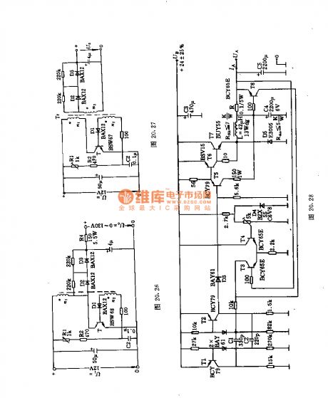
5V~24V/5A adjustable DC voltage converter with current limitting
Published:2011/4/20 21:39:00 Author:May | Keyword: 5V~24V/5A, adjustable, DC voltage converter, current limitting
This circuit adopts three spread fast power transistors BUY55 and fast power diode SSiE3055 as switching component. The control frequency is 20kHz and is out of hearing frequency range. Power supply by 24V storage battery, this circuit can change it to TTL circuit used 5V power supply. It is used in automobile or other industrial circle. Its efficiency is higher than 70%.
Main technical data:
Working voltage: 24±25%V;
Oscillation frequency: ≈20kHz;
Output voltage: 5V (3~6V);
Maximum output noise voltage: 20mV (peak to peak value);
Maximum output current: 5A;
Minimum output current: 0.3A;
Current limiting value: ≈5.5A;
Regulation factor: 0.04. (View)
View full Circuit Diagram | Comments | Reading(498)
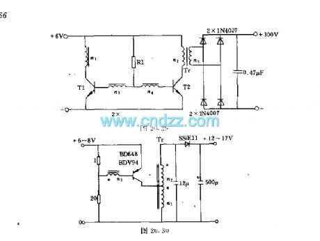
5V-+12V and -15V DC converter
Published:2011/4/20 22:00:00 Author:May | Keyword: 5V-+12V and -15V, DC converter
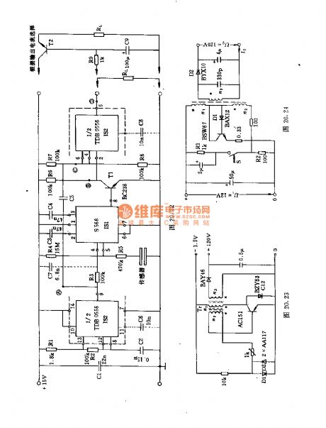
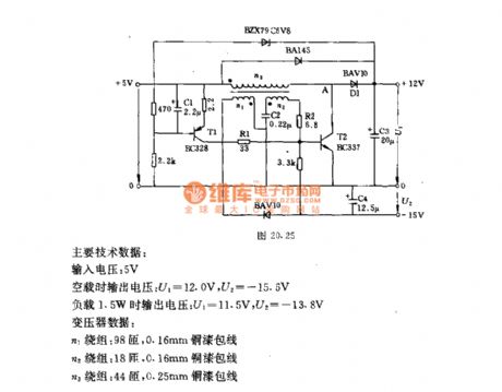
When this circuit is in stable state, capacitor C3 has about 12V voltage, transistor is breaking over, its collector potential is only few tenths of millivolt. So D1 is blocked off. The currents flow to load through transformer secondary winding and transistor T2. Output voltage is feeding back to the base of T1 through BZX79C6V8. The changing of output voltage leads to the change of collector current. And output voltage is stable by the changing of square wave's duty factor.
Main technical data:
Input voltage: 5V;
output voltage when non load: U1=12.0V, U2=-15.6V;
Output voltage when the load is 1.5W: U1=11.5V, U2=-13.8V.
Transformer data:
n1 winding: 98turns, 0.16mm copper enamel wire;
n2 winding: 18turns, 0.16mm copper enamel wire;
n3 winding: 44turns, 0.25mm copper enamel wire.
(View)
View full Circuit Diagram | Comments | Reading(2205)
80V-12V/10A DC voltage converter
Published:2011/4/20 22:08:00 Author:May | Keyword: 80V-12V/10A, DC, voltage converter
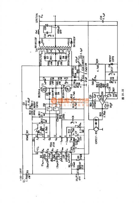
This push pull type converter adopts two SIPMOS transistors BU41A and a piece of integrated circuit TDA4718 as naval vessel network power supply. The input side and output side of converter is isolation. Its working frequency is 50kHz. Its efficiency is 75%. The power supply voltage can change in the range of 56~100V. The output changes to 12V by transformer, then it will pass full wave rectifier of D10, D11, finally, it will smooth to DC by output filter Dr1, C20 and C19.
(View)
View full Circuit Diagram | Comments | Reading(2384)
6V-12V/25W DC voltage converter
Published:2011/4/20 22:17:00 Author:May | Keyword: 6V-12V/25W DC voltage converter
It can adopt single side breaking over converter for low voltage and high power output converter. The oscillation frequency is chose 250Hz in order to decrease the changing loss of transistor AD133.
Main technical data:
Working voltage: 6V (maximum is 8.3V);
Working current: 10A;
Output voltage: 12V;
Output power: 28W;
Efficiency: 46%;
Oscillation frequency: 250Hz.
Transformer data:
n1=20turns, 4×1.0mm copper enamel wire;
n2=40turns, 2×1.0mm copper enamel wire;
n3=8turns, 1.0mm copper enamel wire.
(View)
View full Circuit Diagram | Comments | Reading(2101)
| Pages:440/471 At 20421422423424425426427428429430431432433434435436437438439440Under 20 |
Circuit Categories
power supply circuit
Amplifier Circuit
Basic Circuit
LED and Light Circuit
Sensor Circuit
Signal Processing
Electrical Equipment Circuit
Control Circuit
Remote Control Circuit
A/D-D/A Converter Circuit
Audio Circuit
Measuring and Test Circuit
Communication Circuit
Computer-Related Circuit
555 Circuit
Automotive Circuit
Repairing Circuit