
Basic Circuit
Index 434
The array shape of RRA1608-4R thick film chip resistor
Published:2011/4/28 1:35:00 Author:Ecco | Keyword: thick film , chip, resistor , array shape
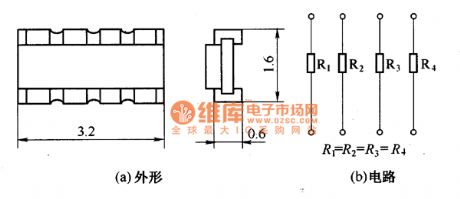
The array shape of RRA1608-4R thick film chip resistor is shown as the chart.
(View)
View full Circuit Diagram | Comments | Reading(474)
USB to 232 circuit
Published:2011/4/11 0:59:00 Author:may | Keyword: USB to 232
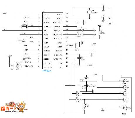
diagram: USB to 232 circuit (View)
View full Circuit Diagram | Comments | Reading(562)
The internal form circuit diagram of double bits LED digital tube
Published:2011/4/28 1:29:00 Author:Ecco | Keyword: internal form , double bits , LED digital tube
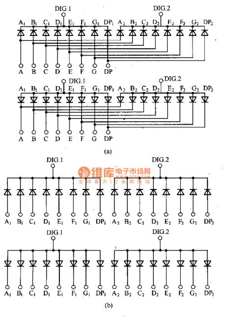
The internal form circuit diagram of double bits LED digital tube is shown as the chart. (View)
View full Circuit Diagram | Comments | Reading(474)
Dual high-speed optocoupler internal circuit diagram
Published:2011/4/28 1:22:00 Author:Rebekka | Keyword: Dual high-speed optocoupler
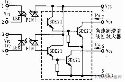
Dual high-speed optocoupler internal circuit diagram is shown as above. (View)
View full Circuit Diagram | Comments | Reading(1642)
BCD code LED digital display components appearance circuit diagram
Published:2011/4/28 1:04:00 Author:Ecco | Keyword: BCD code, LED , digital, display components , appearance
View full Circuit Diagram | Comments | Reading(1155)
Double bits LED digital display appearance circuit diagram
Published:2011/4/28 0:47:00 Author:Ecco | Keyword: Double bits, LED, digital display, appearance

View full Circuit Diagram | Comments | Reading(554)
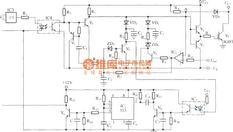
Auto counter for producivity 3
Published:2011/4/25 21:13:00 Author:Ecco | Keyword: Auto counter , producivity
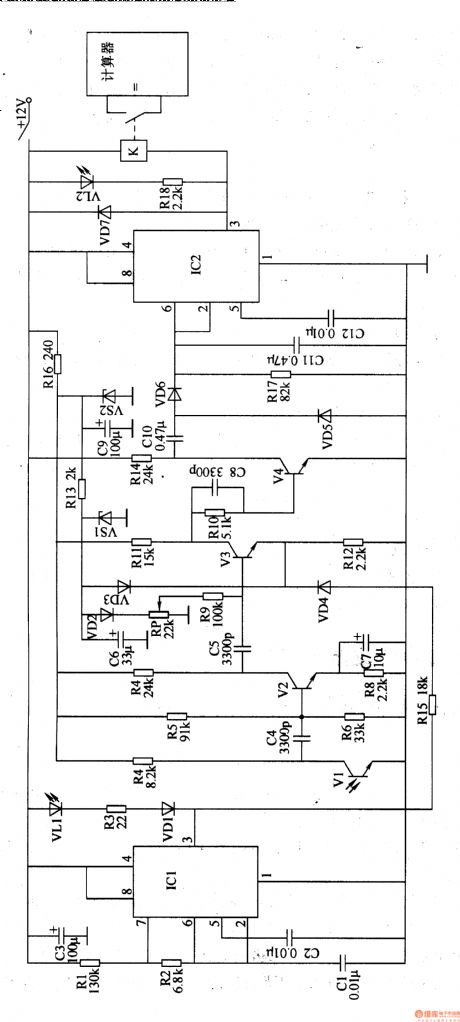
The auto counter for productivity described in the example uses infrared reflection control circuit, it can be used for automatic counting of a variety of assembly line production.
The working principle.
The auto counter for productivity circuit is composed of infrared emission circuit, infrared receiver processing circuit, voltage rectifier circuit, control implementation circuit and the count display circuit, it is shown in Figure 8-83.
Infrared transmitter circuit consists of infrared light-emitting diode VLl, resistors Rl-R3, diode VDl, capacitors CI-C3 and the time-base integrated circuit ICl.
Infrared receiver processing circuit is composed of the infrared phototransistor Vl, transistor V2-V4, resistors R4-R16, capacitors C4-C9, voltage regulator diode VSl, VS2, and potentiometer RP.
Doubler rectifier circuit is composed of the capacitor ClO and Cll, diodes VD5, VD6 and resistors R17.
The control implementation circuit is composed of time base control circuit IC2, resistor R18, diode VD7, capacitor Cl2, light-emitting diodes VL2 and relays K.
(View)
View full Circuit Diagram | Comments | Reading(522)
Winding machine electronic counter 1
Published:2011/4/25 21:29:00 Author:Ecco | Keyword: winding machine , electronic counter
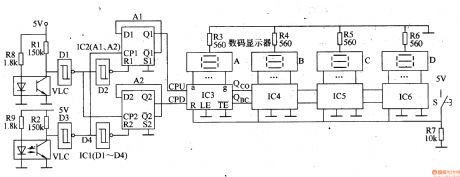
The winding machine electronic counter described in the example has the function of addition, subtraction automated counting, it can be used for transformers, motors, manufacturers restructuring the use of a variety of common winding machine.
The working principle.
The winding machine electronic counter is composed of photoelectric sensor circuit, shaping circuit, plus / minus four-digit identification circuit and counter circuit, it is shown in the figure 8-84.
Photoelectric sensor circuit consists of resistors Rl, R2, R8, R9, and, and optocouplers VLCl, VLC2.
RI, R8 and VLC1 form an addition counting sensor circuit.
R2, R9 and VLC2 sensor form a subtraction count circuit.
Shaping circuit consists of the Dl-D4 inside the six non-gate Schmitt trigger circuit ICl.
Plus / minus identification circuit is composed of the A1,A2 inside the double-D flip-flop IC2.
Four digits counter is composed of the resistors R3-R7, reset button S, counter / decoder IC lC3-1C6 and LED digital display A-D. (View)
View full Circuit Diagram | Comments | Reading(2933)
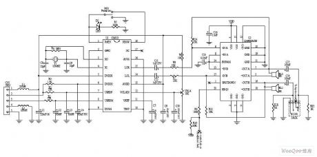
Winding electronic counter 2
Published:2011/4/25 21:39:00 Author:Ecco | Keyword: Winding , electronic counter
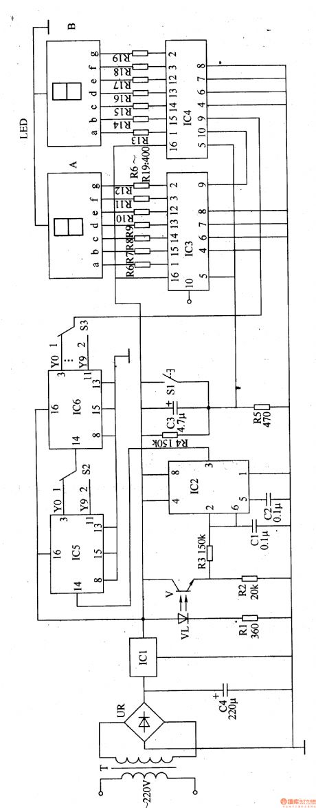
The winding machine electronic counter described in the example uses LED digital display to show the wound coil turns, the use of maximum count rate is 9900 turns.
The working principle
The winding machine circuit is composed of the power circuit, infrared switch circuit, shaping / transformation circuit, reset circuit, divider circuit and the LED counter circuit, it is shown in Figure 8-85.
Power circuit is composed of the power transformer T, rectifier bridge pile UR, filter capacitor C4 and the three-terminal voltage regulator integrated circuit ICl.
Infrared switch circuit consists of infrared light-emitting diodes VL, infrared phototransistor V and resistors Rl and R2.
Plastic / converter integrated circuit is composed of the time base circuit IC2 and resistor R3, capacitor Cl and C2.
The reset circuit is composed of reset button SI, resistors R4, R5 and capacitor C3.
Count divider circuit consists of integrated circuits IC5, 1C6, and override switch S2, S3. LED LED digital display is composed of the counter circuit A & B, resistor R6-Rl9 and counter / decoder integrated circuit IC3, 1C4. (View)
View full Circuit Diagram | Comments | Reading(1996)
Metal detector 5
Published:2011/4/26 4:58:00 Author:Ecco | Keyword: Metal detector
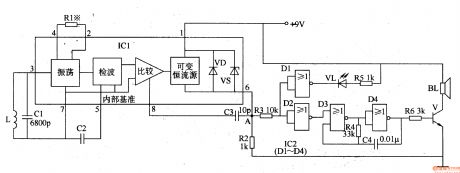
The working principle.The metal detector circuit is composed of sound and light alarm oscillator circuit, it is shown in Figure 8-71.
Oscillator circuit consists of inductor L, capacitor Cl, sensor switch integrated circuit ICl (includes oscillator, detector and comparator circuit, etc.) and the peripheral components. Sound and light alarm circuit consists of four NOR gate integrated circuit lC2 (Dl-D4) and light emitting diode VL, speaker BL and other components. When the inductor (detection coil) L detecting metal objects, the oscillator circuit oscillation, the loss is smaller, the pin 6 of ICl outputs low level, sound and light alarm circuit is not working, VL LED is not lit, the speaker BL does not ring.
When the L detecting metal objects, the oscillator stops, pin 6 of IC1 changes into high level from low level, the DI and D2 inside NOR gate integrated circuit IC2 output low level, the light-emitting diode VL is lit; while enabling the audio oscillator composed of NOR gate D3, D4 and resistor R4, capacitor C4 works, it produces audio oscillator signal which is amplified by the V to drive the speaker BL alarm, and the sound will indicate the user they have detected metal objects. (View)
View full Circuit Diagram | Comments | Reading(2112)
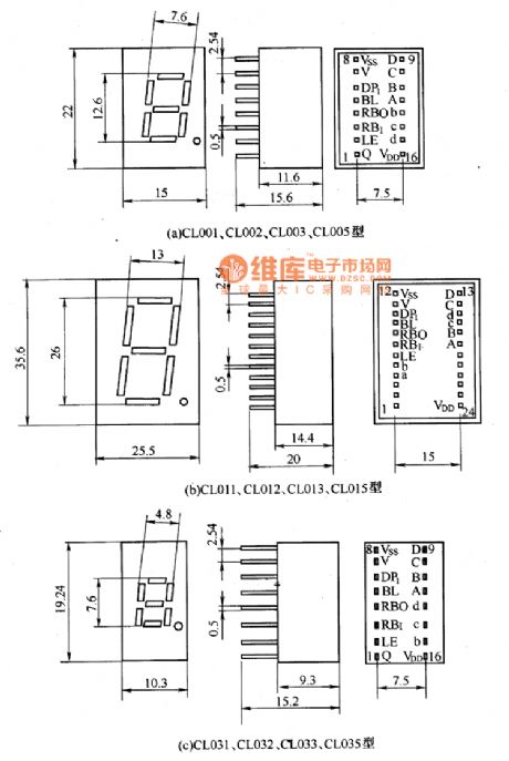
FR series of LED digital display shape circuit diagram
Published:2011/4/27 22:57:00 Author:Ecco | Keyword: FR series , LED digital display , shape
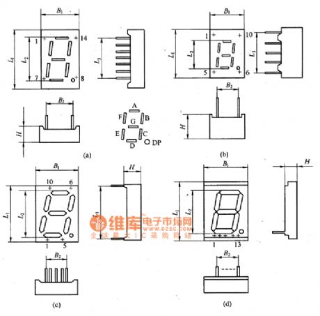
The FR series of LED digital display shape circuit diagram is shown as the chart. (View)
View full Circuit Diagram | Comments | Reading(919)
The structure indicating circuit diagram of glow numerating tube
Published:2011/4/27 22:24:00 Author:Ecco | Keyword: structure indicating , glow numerating tube
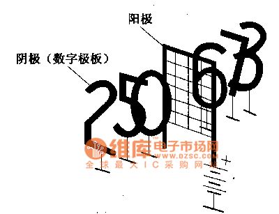
The glow numerating tube
The glow numerating tube is made by the glow discharging principle, the glass tube filled with neon gas is equipped with 10 cathodes with the word of 0,1,2 ... ... 9 and a common anode. The circuit is shown as the chart. The surface area of the cathode is almost the same with each other, but the distance between each anode and the anode is determined based on number of strokes. So under the same anode voltage, the necessary word will be lit by controlling each cathode voltage.
(View)
View full Circuit Diagram | Comments | Reading(594)
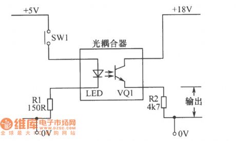
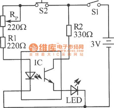
The basic optocoupler circuit diagram
Published:2011/4/27 21:54:00 Author:Ecco | Keyword: basic, optocoupler
View full Circuit Diagram | Comments | Reading(2038)
The glow numerating tube driver circuit diagram
Published:2011/4/27 22:01:00 Author:Ecco | Keyword: glow numerating tube , driver circuit
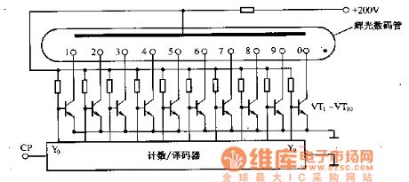
The glow numerating tube can be driven by a strong electric field, so it needs to be equipped with an electronic switch between decoder and the glow digital tube. The circuit is shown as the circuit, the VT1-VT10 is switch circuit composed of the semiconductor transistor.
(View)
View full Circuit Diagram | Comments | Reading(483)
Simple detection circuit diagram of optocoupler
Published:2011/4/27 21:44:00 Author:Ecco | Keyword: Simple, detection , optocoupler
View full Circuit Diagram | Comments | Reading(1911)
The structure indicating diagram of rectangular chip resistor
Published:2011/4/27 21:42:00 Author:Ecco | Keyword: structure indicating , rectangular chip , resistor
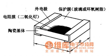
Structure and dimensionsRectangular chip resistors have two types, namely, thick film chip resistors and thin film chip resistors. The thick-film chip resistors are commonly used. The structure of rectangular chip resistors is shown as the chart.
(View)
View full Circuit Diagram | Comments | Reading(686)
Metal detector 4
Published:2011/4/26 4:48:00 Author:Ecco | Keyword: Metal detector
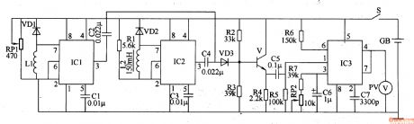
The working principle.The metal detector circuit consists of detection oscillator, reference oscillator, mixer and signal display, it is shown as Figure 8-70.
The detection oscillator circuit is composed of the time base oscillator ICl, inductor Ll, potentiometer RPl, diode VDl and capacitors Cl, C2. Reference oscillator (reference oscillator) circuit is composed of the time-base integrated circuit IC2, inductor L2, diode VD2, resistor Rl and capacitors C3, C4. Mixer is composed of the transistor V, diode VD3 and resistors R2-R4. Signal display circuit consists of integrated circuit IC3, voltage meter RC PV and peripheral components.
Rl-R7 choose 1/4W or 1/8W carbon film resistors. RPl uses synthetic membranes potentiometer with switch; RP2 uses synthetic membrane potentiometer without switch or variable resistor. Cl-C5, C7 use ceramic capacitors; C6 uses the aluminum electrolytic capacitor with the voltage being greater than lOV. VDl-VD3 use 2AP9, 2APlO common germanium germanium diode or 2AK series switching diode. V uses 3DG6 or S9018 silicon NPN transistor.
(View)
View full Circuit Diagram | Comments | Reading(11542)
USB Dual 2.5W multimedia power amplifier circuit diagram
Published:2011/4/27 3:18:00 Author:Rebekka | Keyword: USB Dual 2.5W multimedia power
USB Dual 2.5W multimedia power amplifier circuit diagram is shown as above. (View)
View full Circuit Diagram | Comments | Reading(3307)
Comprehensive Short-circuit Protection Circuit of Decreasing Grid Voltage, Soft Shutoff, and Lowering Operating Frequency
Published:2011/4/21 21:43:00 Author:muriel | Keyword: Comprehensive Short-circuit Protection, Decreasing Grid Voltage, Soft Shutoff, Lowering Operating Frequency
View full Circuit Diagram | Comments | Reading(487)
Nilometer circuit
Published:2011/4/26 22:12:00 Author:Nicole | Keyword: nilometer
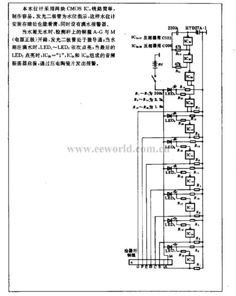
This nilometer adopts two CMOS IC, the circuit is simple and easy to make. LED is as water level indicator, this water level indicator can be saw in dark, and it also set a full water annunciator.
When there is no water in water tank, bronze hoop A-G and M in test rod open, LED is in lightly conducting; when there are full water, LED1~LED7 is lighted up one by one; when the last LED on, IC2b= 1 , the audio oscillator witch is composed of IC2c and IC2d starts to oscillate, it alarms by piezoelectric patches. (View)
View full Circuit Diagram | Comments | Reading(1948)
| Pages:434/471 At 20421422423424425426427428429430431432433434435436437438439440Under 20 |
Circuit Categories
power supply circuit
Amplifier Circuit
Basic Circuit
LED and Light Circuit
Sensor Circuit
Signal Processing
Electrical Equipment Circuit
Control Circuit
Remote Control Circuit
A/D-D/A Converter Circuit
Audio Circuit
Measuring and Test Circuit
Communication Circuit
Computer-Related Circuit
555 Circuit
Automotive Circuit
Repairing Circuit