
Basic Circuit
Index 433
LED digital salient pole appearance circuit diagram
Published:2011/4/29 0:37:00 Author:Ecco | Keyword: LED , digital, salient pole , appearance
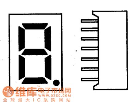
The light-emitting diode display is also known as LED digital display, it uses the feature, which light-emitting diodes will be lit by flowing certain current under forward voltage, the seven segment LED being packaged will become a LED digital display. Its shape is shown as the chart.
(View)
View full Circuit Diagram | Comments | Reading(514)
Two RY927 league level applications circuit diagram
Published:2011/4/28 22:55:00 Author:Ecco | Keyword: Two , league level , application
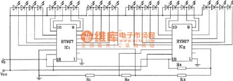
When RY927 is using cascadedly, it needs to connect the related input ends according to the chart. The connecting method is the same when there are more than two stages. It should be noted that RY927 allows seven cascaded as maximum, and it can drive 84 LED at best. Besides the above applications, it can also constitute the automatic dimming, speed tables and so on. If it requires less precision, it can also be used for voltage indication, field instruction and other circuits.
(View)
View full Circuit Diagram | Comments | Reading(579)
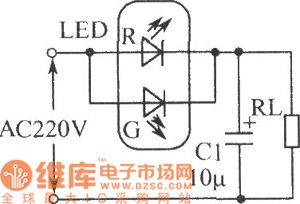
Relay status indication circuit diagram
Published:2011/4/29 1:15:00 Author:Ecco | Keyword: Relay, status indication
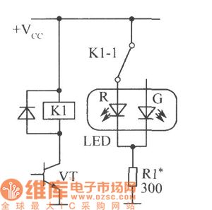
Figure shows the relay status indication circuit. The relay has one or more sets of contacts, If the public end of a group of contacts connects to VDD, the public end will connect to normally closed contacts in releasing state, and LED-R emits red light; the public end will connect to normally open contacts in pulling state, and LED-G emits green light.
(View)
View full Circuit Diagram | Comments | Reading(564)
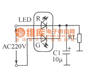
LED full-wave rectifier circuit
Published:2011/4/29 1:16:00 Author:Ecco | Keyword: LED , full-wave , rectifier
View full Circuit Diagram | Comments | Reading(618)
LED half-wave rectifier circuit
Published:2011/4/29 1:19:00 Author:Ecco | Keyword: LED, half-wave , rectifier
View full Circuit Diagram | Comments | Reading(653)
High voltage following circuit diagram
Published:2011/4/28 22:34:00 Author:Ecco | Keyword: High voltage , following
High voltage following circuit diagram is shown as the chart. (View)
View full Circuit Diagram | Comments | Reading(542)
Analog turning disc guessing award device circuit diagram
Published:2011/4/28 21:39:00 Author:Ecco | Keyword: Analog, turning disc , guessing award device
View full Circuit Diagram | Comments | Reading(621)
Playing football game circuit diagram
Published:2011/4/28 22:18:00 Author:Ecco | Keyword: Playing football game
View full Circuit Diagram | Comments | Reading(1449)
Tracking sun photoelectric servo circuit used in chromospheric telescope
Published:2011/4/28 21:01:00 Author:Nicole | Keyword: photoelectric servo, chromospheric telescope
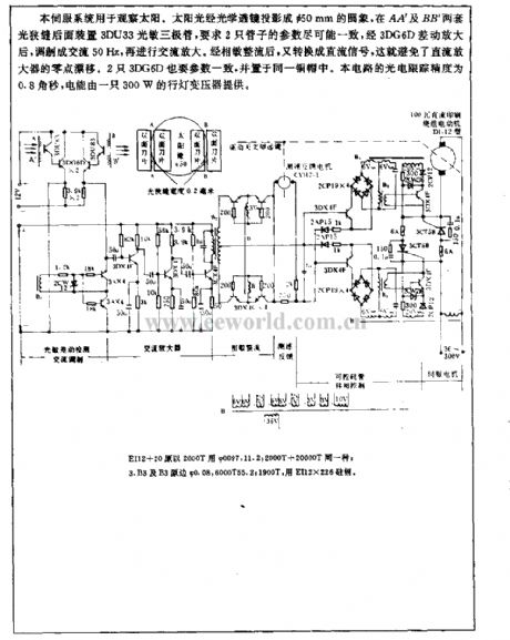
This servo system is used to observe sun. The sunshine is projected onto a Φ50mm round image by optical lens, to fix a 3DU33 photosensitive transistor to the later light slit of AA' and BB', it requires the parameters of two tubes should be as nearly as possible, after 3DG6D differentail amplifier, it is modulated into AC 50Hz, then it is AC amplified. After phase-sensitive rectification, it will be changed into DC singal, it can avoid the zero drift of DC amplifier. The parameters of two 3DG6D also should be coincided, and they are put into the same copper cap. The photoelectric tracing precision of this circuit is 0.8arc-second, the electrical energy is provided by a 300W portable lamp transformer. (View)
View full Circuit Diagram | Comments | Reading(2041)
The typical application circuit diagram of RY927 multi-segment LED driver linear display
Published:2011/4/28 21:12:00 Author:Ecco | Keyword: typical application , multi-segment, LED , driver , linear display
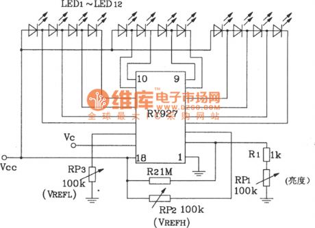
RY927 multi-segment LED driver linear display
(View)
View full Circuit Diagram | Comments | Reading(652)
20-bit LED dot / line conversion display circuit diagram composed of two LM3914
Published:2011/4/28 21:03:00 Author:Ecco | Keyword: 20-bit, LED, dot, line, conversion , display , two
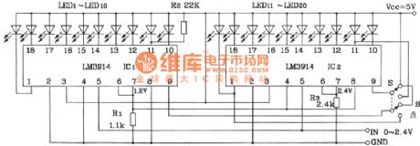
20-bit LED dot / line conversion display circuit diagram composed of two LM3914
(View)
View full Circuit Diagram | Comments | Reading(2916)
VU meter circuit diagram composed of M3916
Published:2011/4/28 20:49:00 Author:Ecco | Keyword: VU meter
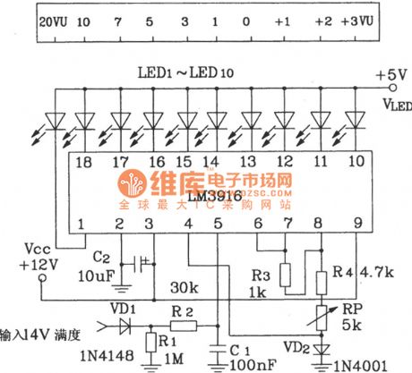
VU meter circuit diagram composed of M3916
(View)
View full Circuit Diagram | Comments | Reading(1828)
About alternating-current bridge Symmetric incentive circuit
Published:2011/4/2 4:12:00 Author:may | Keyword: alternating-current bridge, Symmetric incentive
About alternating-current bridge Symmetric incentive circuit is show in the following picture:
(View)
View full Circuit Diagram | Comments | Reading(639)
Bar code reading circuit
Published:2011/4/28 1:33:00 Author:Nicole | Keyword: Bar code, reading
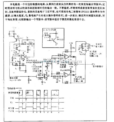
This circuit is sensitive to edge, every change from black to white or white to black will output narrow pulse; the timing figure shows that it is in accordance with the bar code parrent output. Whatever temperature, environmental lighting or pattern background is, DC servo remain Q1 base's DC level comstant. It also can use photodiode and 2N2222 transistor as sensor to enlarge the width. The amplified differential signal produced by Q2 collector is magnified further by IC2, feeding it to double threshold value comparator. About each mutation, the comparator will output a narrow pulse, this narrow pulse is suitable for feeding to microprocessor. (View)
View full Circuit Diagram | Comments | Reading(702)
TTL LED driver circuit diagram
Published:2011/4/28 2:27:00 Author:Ecco | Keyword: TTL, LED driver
View full Circuit Diagram | Comments | Reading(1667)
The LED driver circuit diagram with CMOS op amp
Published:2011/4/28 2:25:00 Author:Ecco | Keyword: LED driver , CMOS op amp
View full Circuit Diagram | Comments | Reading(698)
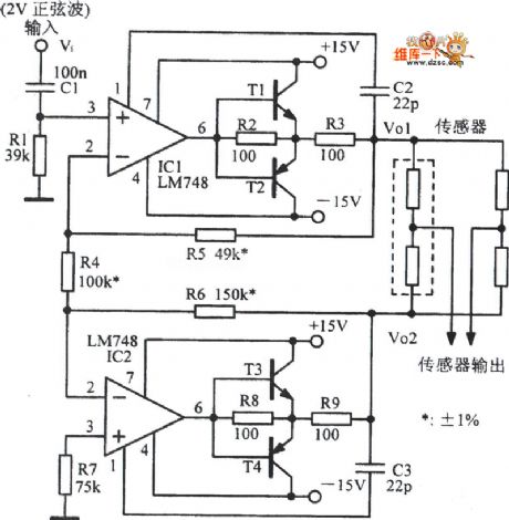
Analog signals isolation circuit
Published:2011/4/11 2:59:00 Author:may | Keyword: Analog signals isolating
Analog signals isolation circuit is shown in the diagram:
(View)
View full Circuit Diagram | Comments | Reading(2929)
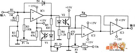
The typical application circuit of LC901 integrated circuit
Published:2011/4/28 2:01:00 Author:Ecco | Keyword: typical application circuit , integrated circuit
The typical application circuit of LC901 integrated circuit is shown as the chart. (View)
View full Circuit Diagram | Comments | Reading(781)
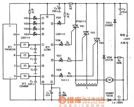
SN55476~SN55479 dual peripheral driver circuit
Published:2011/4/24 1:24:00 Author:May | Keyword: dual peripheral driver
SN55476~SN75479 is high voltage, strong current and fast switch time double peripheral drive. Its output current is 300mA, output voltage is high, switch speed is fast, it has output clamp diode, input end with TTL and MOS circuit is consistent, it is very suitable for hammer driver. The connect lineof SN55477 using as lamp driver is shown in the diagram.
(View)
View full Circuit Diagram | Comments | Reading(896)
RTD cold junction compensation thermocouple input circuit composed of XTR101
Published:2011/4/1 2:19:00 Author:may | Keyword: TD cold junction compensation thermocouple input
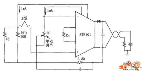
This circuit use J type RTD. Its resistance value corresponding to the temperature can be checked through at RTD factory offered table. It uses 20Ω zero adjustment potentiometer to zero point correction.
(View)
View full Circuit Diagram | Comments | Reading(1175)
| Pages:433/471 At 20421422423424425426427428429430431432433434435436437438439440Under 20 |
Circuit Categories
power supply circuit
Amplifier Circuit
Basic Circuit
LED and Light Circuit
Sensor Circuit
Signal Processing
Electrical Equipment Circuit
Control Circuit
Remote Control Circuit
A/D-D/A Converter Circuit
Audio Circuit
Measuring and Test Circuit
Communication Circuit
Computer-Related Circuit
555 Circuit
Automotive Circuit
Repairing Circuit