
Basic Circuit
Index 431
The timing responder circuit diagram
Published:2011/5/3 3:24:00 Author:Ecco | Keyword: timing responder
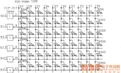
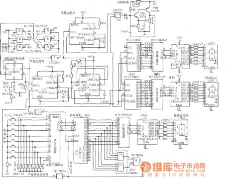
The circuit is shown as the circuit, the timing responder circuit is composed of the following parts: (1) clock pulse oscillation circuit. IC3 and its peripheral components form oscillator, period T = 1s. (2)display, light-emitting circuit (3) answer brake circuit (4) the end of the brake circuit when walking (5) resetting start (6) second frequency LED circuit:
(View)
View full Circuit Diagram | Comments | Reading(816)
BSR (G) series of unit digital display outline and circuit diagram
Published:2011/5/3 3:31:00 Author:Ecco | Keyword: BSR (G) series , unit, digital display , outline
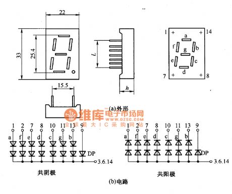
BSR (G) series of unit digital display outline and circuit diagram is shown as the chart. The main parameters are in Table.
BSR (G) series of unit digital display outline and circuit diagram is shown as the chart. (View)
View full Circuit Diagram | Comments | Reading(749)
TA31002 ringing integrated circuit diagram
Published:2011/5/3 3:41:00 Author:Ecco | Keyword: ringing, integrated circuit
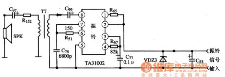
TA31002 is ringing integrated circuit produced by Toshiba, it is widely used in the communications equipment.
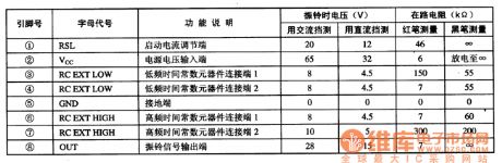
1. pin functions and data TA31002 IC uses 8-pin dual in-live-style package, the pin functions and data are listed in Table 1. Table 1 lists TA31002 IC pin functions and data.
2. A typical application circuit The typical bell application circuitcomposed of TA31002 integrated circuit is shown in Figure 1. Figure 1 shows typical application circuit of TA31002 integrated circuit.
(View)
View full Circuit Diagram | Comments | Reading(1756)
Simple square wave generator circuit
Published:2011/3/17 23:10:00 Author: | Keyword: square wave generator
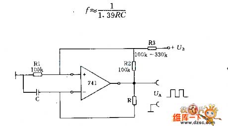
In the circuit parameter R1, R2 and R3 can adjust according to concrete condition, and osillator frequency decided to
(View)
View full Circuit Diagram | Comments | Reading(0)
Light load energy-saving process circuit diagram
Published:2011/5/3 3:05:00 Author:Rebekka | Keyword: Light load, energy-saving process
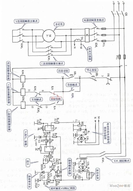
Light load energy-saving process circuit diagram. (View)
View full Circuit Diagram | Comments | Reading(935)
ECl89 internal circuit and typical application circuit diagram
Published:2011/5/3 3:04:00 Author:Ecco | Keyword: internal circuit , typical application
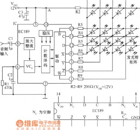
The working principle is shown in Fig. It shows the internal circuit diagram and typical application circuit of EC189 4 × 4 dot matrix sound and light control circuit. It is mainly composed of the amplification circuit / rectifier, voltage-controlled oscillator (VC0), counter / decoder, drive and power supply voltage regulator and other components.
(View)
View full Circuit Diagram | Comments | Reading(798)
Negative sequence voltage-phase protection circuit diagram
Published:2011/5/3 3:04:00 Author:Rebekka | Keyword: Negative sequence, voltage-phase protection
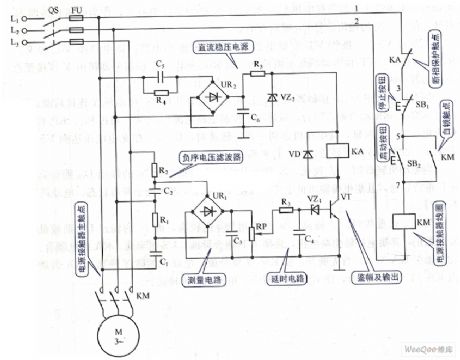
Negative sequence voltage-phase protection circuit diagram. (View)
View full Circuit Diagram | Comments | Reading(1419)
Line current zero-phase protection circuit diagram
Published:2011/5/3 3:03:00 Author:Rebekka | Keyword: zero-phase protection, Line current

Line current zero-phase protection circuit diagram. (View)
View full Circuit Diagram | Comments | Reading(1145)
Low power DC speed governing circuit diagram
Published:2011/5/3 2:51:00 Author:Rebekka | Keyword: Low power DC, speed governing
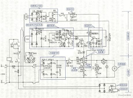
Low power DC speed governing circuit diagram. (View)
View full Circuit Diagram | Comments | Reading(593)
HTJD4105C、NTJD4401N Internal Circuit
Published:2011/5/3 2:41:00 Author:Felicity | Keyword: Internal Circuit
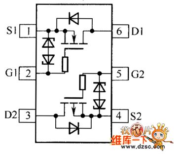
NTJD4105C、NTJD4401C Internal Circuit is showed in the piture above. (View)
View full Circuit Diagram | Comments | Reading(676)
Power bridge temperature protection relay circuit diagram
Published:2011/5/3 2:33:00 Author:Rebekka | Keyword: Power bridge, temperature protection relay

Power bridge temperature protection relay circuit diagram. (View)
View full Circuit Diagram | Comments | Reading(925)
Fluorescence digital tube structure indicating circuit diagram
Published:2011/5/3 2:23:00 Author:Ecco | Keyword: Fluorescence, digital tube , structure , indicating
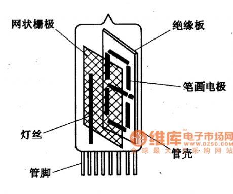
Fluorescence digital tube structure indicating circuit diagram is shown as the chart.
(View)
View full Circuit Diagram | Comments | Reading(516)
Fahrenheit Thermometer Principle Circuit
Published:2011/5/3 2:10:00 Author:Felicity | Keyword: Fahrenheit Thermometer Principle Circuit,
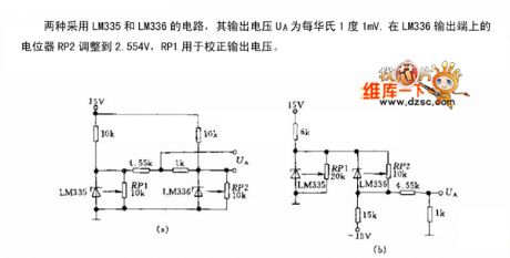
Fahrenheit Thermometer Principle Circuit is showed in the picture above. (View)
View full Circuit Diagram | Comments | Reading(615)
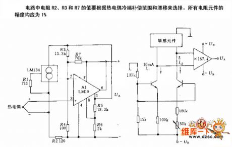
Principle Circuit of Medical Thermometer
Published:2011/5/3 2:13:00 Author:Felicity | Keyword: Principle Circuit of Medical Thermometer ,
Principle Circuit of Medical Thermometer is showed in the picture above. (View)
View full Circuit Diagram | Comments | Reading(1081)
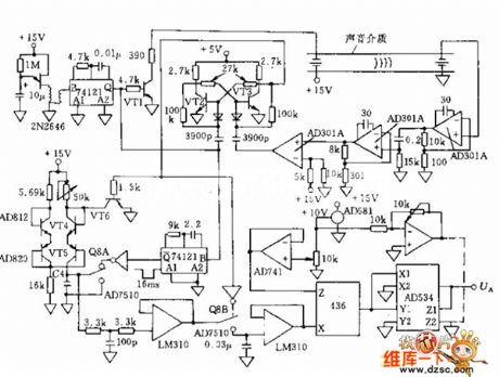
Principle Circuit of Temperature Measurement
Published:2011/5/3 2:17:00 Author:Felicity | Keyword: Principle Circuit of Temperature Measurement,
Principle Circuit of Temperature Measurement is showed in the picture above. (View)
View full Circuit Diagram | Comments | Reading(640)
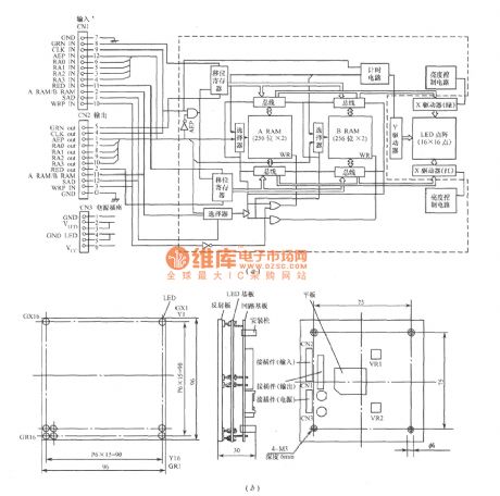
16 × 16, Φ5mm spot color dot matrix structure and box circuit diagram
Published:2011/5/3 2:15:00 Author:Ecco | Keyword: 16 × 16, Φ5mm , spot , color , dot matrix , structure, box
View full Circuit Diagram | Comments | Reading(472)
New timer switch circuit diagram
Published:2011/5/3 2:06:00 Author:Ecco | Keyword: New , timer , switch
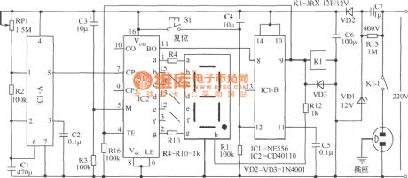
The new timer switch circuit has the variable time adjusting function, it also has a countdown show feature, which shows the remaining regular time of the circuit at any time, therefore it is especially useful. The entire circuit is simple, easy to make, easy to use, suitable for installation in a variety of occasions. IC1 model is NE556 (NE555 can also use the two chips to instead). IC2 model is CD40110. The digital tube should use common cathode and high brightness LED. C1 uses the oil capacitor with the voltage in 400V, the capacity in 1μF . K1 uses the JRX-13F relay with pull-in voltage in 12V (to improve contact capacity, you can use two sets of normally open contacts in parallel). RP1 uses 0.5W ~ 1W shank potentiometer. S1 uses pole button switch. The remaining components are shown as the chart.
(View)
View full Circuit Diagram | Comments | Reading(1088)
DC-AC thin power meter appearance circuit diagram
Published:2011/5/3 1:45:00 Author:Ecco | Keyword: DC, AC , thin, power meter , appearance
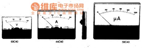
DC-AC thin power meter is a new electric meter, which uses an ideal supporting structure of silk sheets, with good resistance to vibration and impact capacity. Thickness is below I5mm, and it is suitable for miniaturization and integration of electronic equipment, instruments, communications equipment and radio equipment, it is is the replacements of mounted meter.
(View)
View full Circuit Diagram | Comments | Reading(510)
DC-AC installed power meter appearance circuit diagram
Published:2011/5/3 1:38:00 Author:Ecco | Keyword: DC, AC , installed power meter, appearance
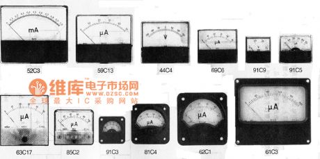
DC-AC installed power meter appearance is shown as the chart.
(View)
View full Circuit Diagram | Comments | Reading(491)
AC power supply working status indication circuit
Published:2011/5/3 1:19:00 Author:Ecco | Keyword: AC power supply , working status , indication circuit
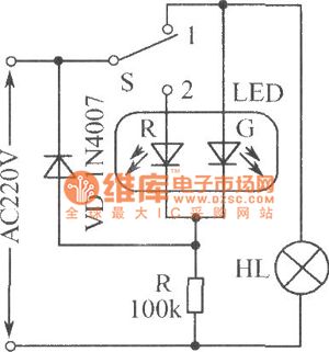
AC power working condition indicating circuit is shown as the chart, S is the 2 S 1 switch, when S is set to 1 position, the bulb HL gets power and emits light, while LED-G emits green light and it is used as the load working instructions; when the S sets 2 bit, HL is off, LED-G is extinguished, only the LED-R emits red light, which is used as indicating mains supply.
(View)
View full Circuit Diagram | Comments | Reading(566)
| Pages:431/471 At 20421422423424425426427428429430431432433434435436437438439440Under 20 |
Circuit Categories
power supply circuit
Amplifier Circuit
Basic Circuit
LED and Light Circuit
Sensor Circuit
Signal Processing
Electrical Equipment Circuit
Control Circuit
Remote Control Circuit
A/D-D/A Converter Circuit
Audio Circuit
Measuring and Test Circuit
Communication Circuit
Computer-Related Circuit
555 Circuit
Automotive Circuit
Repairing Circuit