
Basic Circuit
Index 427
EIA-422-A input protection circuit diagram
Published:2011/5/5 9:31:00 Author:Rebekka | Keyword: input protection
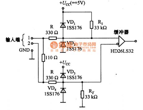
The figure shows two signal lines transmit digital signal EIA-422-A input protection circuit. Resistor R and diode VD1 ~ VD2 are used for protection. (View)
View full Circuit Diagram | Comments | Reading(1492)
Memory integrated circuit diagram
Published:2011/5/5 20:49:00 Author:Ecco | Keyword: Memory, integrated circuit
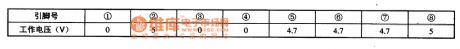
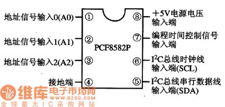
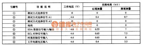
PCF8582P is the memory integrated circuit produced by Philips, it is widely used in color television sets, audio, DVD players, air-conditioning system control circuit. 1. Features of functionIt is composed of some of the subsidiary function circuit. 2. Pin functions and data PCF8582P IC is packaged with 8-pin in double rows, the pin functions are shown in the figure, the operating voltage is listed in Table. PCF8582P IC pin function PCF8582P integrated circuit working voltage
(View)
View full Circuit Diagram | Comments | Reading(846)
PCF8581P I2C bus control memory integrated circuit diagram
Published:2011/5/5 20:44:00 Author:Ecco | Keyword: I2C , bus control, memory , integrated
PCF8581P is the I2C bus control electricity erasable reading memory integrated circuit produced by Philips, it is widely used in large screen color TV and other video, audio, air conditioners and other micro-computer control system. 1. Features of function PCF8581P IC is embedded CMOS 8 Kbit E2PROM read memory and I2C bus control interface circuit. Typical application circuit is shown as the figure. 2. Pin functions and data PCF8581P integrated circuit uses 8-pin dual in-line package, the pin functions and data are listed in Table. PCF8581P IC pin functions and data
(View)
View full Circuit Diagram | Comments | Reading(642)
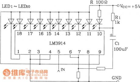
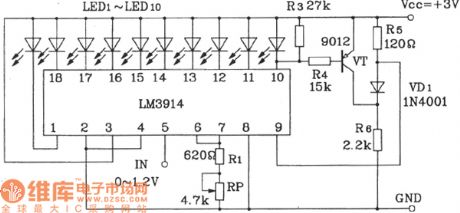
0 ~ 5V line graph indicator circuit diagram
Published:2011/5/5 4:04:00 Author:Ecco | Keyword: 0 ~ 5V , line graph, indicator
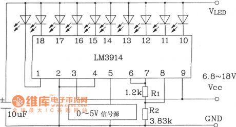
0 ~ 5V line graph indicator circuit composed of LM3914 series of point / line LED display driver integrated circuit.
LM3914LED display driver IC is widely used, the external components and wiring changes may constitute a variety of display and alarm circuits, cascade using may constitute a multi-level LED display.
(View)
View full Circuit Diagram | Comments | Reading(1569)
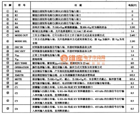
UM9169 microcomputer dialing integrated circuit diagram
Published:2011/5/5 8:50:00 Author:Nicole | Keyword: microcomputer, dialing
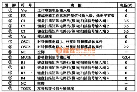
UM9169 is microcomputer dialing integrated circuit. It is used in all kinds of communication telephones.
1, functions and features
UM9169 integrated circuit contains double audio frequency dialing singal process circuit, key switch singal encoding and decoding and squelch control circuit.
2, pin function and data
UM9169 integrated circuit's pin function and data is shown in the table 1-1.
(View)
View full Circuit Diagram | Comments | Reading(612)
TB2003-004FN system control microcomputer integrated circuit
Published:2011/5/5 8:20:00 Author:TaoXi | Keyword: system control, microcomputer
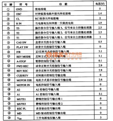
The TB2003-004FN system control microcomputer integrated circuit is produced by the TOSHIBA company, and it can be used in the top grade walkman cassette player applications, and the pin functions and data is as shown in table 1.
Table1 The pin functions and data of the TB2003-004FN (View)
View full Circuit Diagram | Comments | Reading(671)
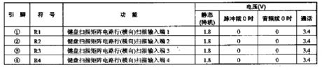
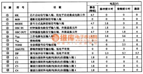
UM91210 microcomputer dialing integrated circuit diagram
Published:2011/5/5 8:33:00 Author:Nicole | Keyword: microcomputer, dialing
UM91210 is microcomputer dialing integrated circuit. It is used in all kinds of communication telephones.
UM91210 integrated circuit contains pulse/double audio frequency compatible dialing, key switch singal encoding and decoding circuit and so on, the integrated circuit's pin function and data are shown in the excel 1-1.
(View)
View full Circuit Diagram | Comments | Reading(647)
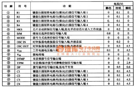
HM91230C/D microcomputer single chip dialing integrated circuit diagram
Published:2011/5/5 8:36:00 Author:Nicole | Keyword: microcomputer, single chip dialing
UM91230C、UM91230D are microcomputer single chip dialing integrated circuits which are produced by United Micro Company, as dialing circuit, it is used in communication equipment. This IC adopts 22-foot dual in-line package, the integrated circuit's pin function and data are shown in the excel 1-1.
(View)
View full Circuit Diagram | Comments | Reading(663)
UM91260A/C microcomputer single chip dialing integrated circuit diagram
Published:2011/5/5 8:27:00 Author:Nicole | Keyword: microcomputer, single chip dialing
UM91260A、UM91260C are microcomputer dialing integrated circuit, as dialing circuit, it is used in communication equipment.
UM91260A、UM91260C have the function of: re-dial 32 bits numbers(double audio type is 31 bits), store 10 16-bit numbers, the integrated circuit's pin function and data are shown in the excel 1-1.
(View)
View full Circuit Diagram | Comments | Reading(487)
PPU6528 video processing integrated circuit diagram
Published:2011/5/5 4:17:00 Author:Ecco | Keyword: video , processing , integrated circuit
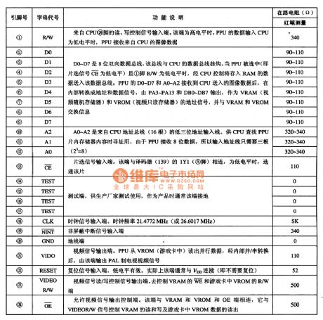
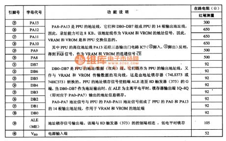
PPU6528 is a single-chip video signal processing integrated circuit, which is widely used in game consoles. 1. Features of functionPPU6528 IC includes bi-directional data bus interface circuit, clock circuit, reset circuit, the address line-side interface circuit, video signal processing circuit, the read / write control circuit, and other ancillary functions circuit. 2. Pin functions and data It uses a 40-pin dual in-line package, the pin functions and data are listed in Table. PPU6528 IC pin functions and data
(View)
View full Circuit Diagram | Comments | Reading(814)
5-point in a line LED display driver circuit diagram composed of TA7654P/TA7655P
Published:2011/5/5 4:25:00 Author:Ecco | Keyword: 5-point , in a line , LED , driver , display
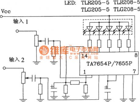
5-point in a line LED display driver circuit diagram composed of TA7654P/TA7655P (View)
View full Circuit Diagram | Comments | Reading(957)
The LED display circuit diagram with flashing alarm
Published:2011/5/5 3:59:00 Author:Ecco | Keyword: LED display circuit , flashing alarm
The LED display circuit diagram with flashing alarm composed of LM3914 series of point / line LED display driver integrated circuit.
(View)
View full Circuit Diagram | Comments | Reading(2787)
TA7315BP frequency conversion switch integrated circuit diagram
Published:2011/5/5 3:37:00 Author:Ecco | Keyword: Frequency conversion , switch , integrated circuit
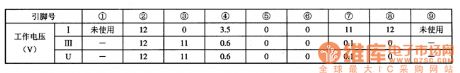
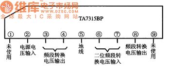
TA7315BP is the frequency conversion switch integrated circuit produced by Toshiba, it is widely used in various screen color TV remote control system for frequency selection. 1. Features of functionTA7315BP IC embedded frequency conversion control signal decoding circuit, decoding driver control circuit and other auxiliary functions circuit. 2. Pin functions and dataTA7315BP integrated circuit uses 9 feet inline package, the pin functions are shown in Figure 1, the typical operating voltage is shown in Table 1. Figure 1 shows TA7315BP IC pin functions, table 1 shows the typical operating voltage of TA7315BP integrated circuit.
(View)
View full Circuit Diagram | Comments | Reading(532)
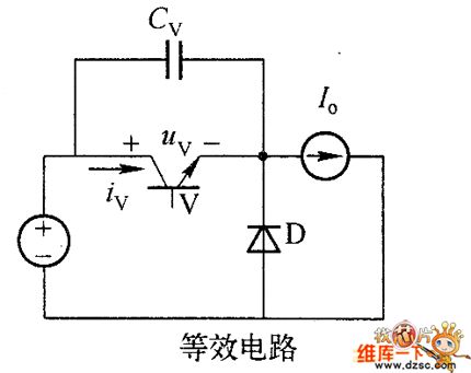
Chopper IGBT
Published:2011/5/5 2:59:00 Author:muriel | Keyword: Chopper, IGBT
Although theswitching devices internal operation mechanismis different ,forthe buffer circuit, itcan only considerthe external characteristic of the device, when IGBT isclosing, the modelis current source of thevoltage control, when it is opening, the model is thevoltage source of voltage control. As shown in figure of chopper is generally IGBT buffer circuit model. (View)
View full Circuit Diagram | Comments | Reading(982)
Dot, line overflow LED display circuit diagram composed of LM3914
Published:2011/5/5 3:10:00 Author:Ecco | Keyword: dot, line overflow, LED , display circuit
Dot, line overflow LED display circuit composed of LM3914 is shown as the chart.
This circuit shows working mode when there is no overflow. When the degree is overflow, LED display changes into line mode, thus indicating overflow. (View)
View full Circuit Diagram | Comments | Reading(1929)
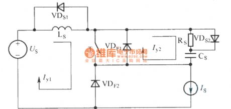
Heteropolarity Turn-Off Absorption Circuit
Published:2011/5/5 1:39:00 Author:Robert | Keyword: Heteropolarity, Turn-Off, Absorption
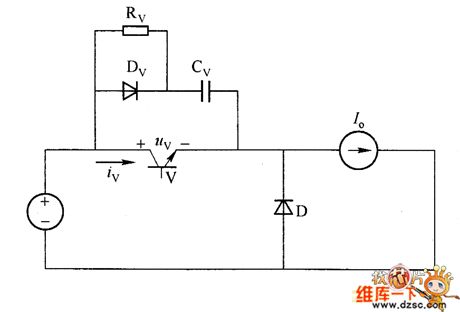
The picture 1 shows the heteropolarity turn-off absorption circuit which has a capacitor in parallel with the switch. When the switch is conducted, the capacitor Cv discharges quickly through the switch V, which makes the switch's additional current large during the conducting moment, and this could damage the switch. To avoid this situation, the pratical shutdown absorption circuitis RCD networks. It is called heteropolarity turn-Off absorption circuit because there are diodes in it. The picture 2 shows the polarized snubber circuit -- application of RCD networks in buck converter, and it is in parallel with the switch.
The compositionof the RCDis using a resistance Rv in parallel with a diode Dv, then take them in series with a capacitor Cv. The Rv's function is limit the Cv's discharging current when the swith is conducted, and also it transfers the energy in Cv to the resistance Rv to be consumed away. The diode Dv's function is making Cv be charged through the diode Dv when the switch is closed, and also the Rv coube be shorted by Dv.
(View)
View full Circuit Diagram | Comments | Reading(1203)
The typical application circuit diagram of LB140 5-bit LED level indicating driver IC
Published:2011/5/5 3:04:00 Author:Ecco | Keyword: typical application circuit , 5-bit , LED level , indicating , driver IC
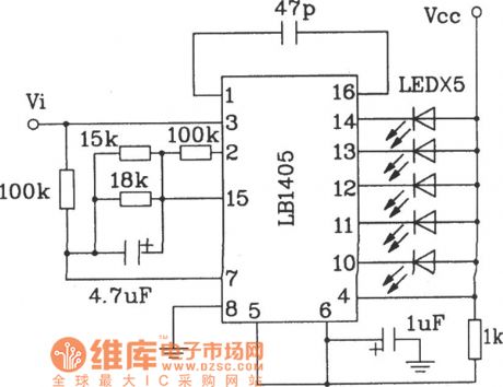
The typical application circuit diagram of LB140 5-bit LED level indicating driver IC is shown as the chart, it iswidely used inrecorders and tape recorders to do the level indicating.
(View)
View full Circuit Diagram | Comments | Reading(1348)
KA2213 single chip sound recorder or reproducer integrated circuit diagram
Published:2011/5/5 2:50:00 Author:Nicole | Keyword: single chip, sound recorder or reproducer
KA2213 is a single chip record and play back integrated circuit which is produced by South Korea's Samung, it is used in recorder and unit audio.
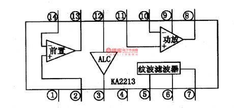
1, KA2213 internal circuit block diagram and pin function
KA2213 internal block contains a record and play back preamplifier, a power amplifier circuit, a automatically gain control circuit(ALC)and ripple filter circuit. The internal block internal circuit block diagram is shown in the figure 1-1. Reading IC adopts 14-foot dual in-line package, it has cooling ribs. The integrated circuit pin function and data is shown in the chart 1-1.
Figure 1-1, the internal block internal circuit block diagram is shown.
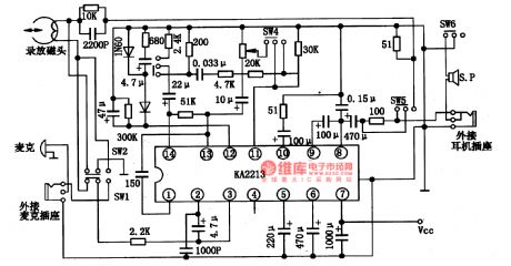
2, KA2213 typical application circuit
KA2213 internal block typical application circuit is shown in the figure 1-2. The figure has no flux imbalance circuit. SW1-SW6 is record and play back switch, the graphic position is in sound-reproducing state.
Figure 2-2, KA2213 internal block typical application circuit (View)
View full Circuit Diagram | Comments | Reading(3431)
UV sensor basic circuit
Published:2011/5/5 2:51:00 Author: | Keyword: UV sensor, basic
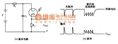
The basic circuit of UV sensor and it's output waveform is as shown in the picture, in which R1and C1 form the charge and discharge loop circuit. It's time constant is called damping time constant.The decay time of electrode residual ion is generally 5-10ms. When the incident UV flux is below a certain value, there can be obtained a number of pulses from the output proportional to those from the incident flux, but if the flux is larger than this value, due to C1's discharge, the tube current is saturated. Therefore, the UV sensor is suitable to be used as photoelectric switch, while not suitable for precision UV measurement. (View)
View full Circuit Diagram | Comments | Reading(1081)
The ring flasher principle circuit diagram
Published:2011/5/5 2:41:00 Author:Ecco | Keyword: ring flasher , principle
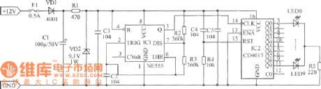
The circuit shown as the chart is the ring scintillator, it is mainly composed of the NE555, CD4017 and external circuit. NE555 constitutes a multivibrator, its square wave output from pin 3 will control CD4017 decoding output shift to turn on LEDs one by one, so that the LEDs flash in ring. The line flicker frequency shown as the chart is about 1.5Hz, operating current is less than 50mA. Component selection: IC1 selects 555 time base circuit, IC2 selects CD4017 integrated circuit. R1 selects (1 / 2) W metal film resistor, the other resistors choose (1 / 4) W resistors, LED0 ~ LED9 can select Φ5mm super bright red LED. Other components are shown as the chart. (View)
View full Circuit Diagram | Comments | Reading(648)
| Pages:427/471 At 20421422423424425426427428429430431432433434435436437438439440Under 20 |
Circuit Categories
power supply circuit
Amplifier Circuit
Basic Circuit
LED and Light Circuit
Sensor Circuit
Signal Processing
Electrical Equipment Circuit
Control Circuit
Remote Control Circuit
A/D-D/A Converter Circuit
Audio Circuit
Measuring and Test Circuit
Communication Circuit
Computer-Related Circuit
555 Circuit
Automotive Circuit
Repairing Circuit