
Basic Circuit
Index 426
Transistor PK130F40 internal circuit
Published:2011/5/8 20:42:00 Author:Christina | Keyword: Transistor, internal circuit
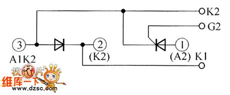
The Transistor PK130F40 internal circuit is as shown:
(View)
View full Circuit Diagram | Comments | Reading(412)
Transistor PK160F120 internal circuit
Published:2011/5/8 19:17:00 Author:Christina | Keyword: Transistor, internal circuit

The Transistor PK160F120 internal circuit is as shown:
(View)
View full Circuit Diagram | Comments | Reading(455)
Transistor PK160F160 internal circuit
Published:2011/5/8 19:16:00 Author:Christina | Keyword: Transistor, internal circuit

The Transistor PK160F160 internal circuit is as shown:
(View)
View full Circuit Diagram | Comments | Reading(436)
Transistor PK160F80 internal circuit
Published:2011/5/8 19:14:00 Author:Christina | Keyword: Transistor, internal circuit

The Transistor PK160F80 internal circuit is as shown:
(View)
View full Circuit Diagram | Comments | Reading(467)
Simple audio power meter circuit diagram composed of LM3915
Published:2011/5/6 3:26:00 Author:Ecco | Keyword: Simple , audio power meter
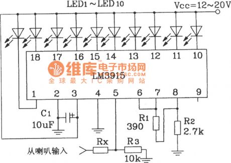
Simple audio power meter circuit diagram composed of LM3915 Note: If the internal resistance of speaker is 4Ω, Rx takeS 10kΩ; the internal resistance is 8Ω, Rx takes 18kΩ, internal resistance is 16Ω, Rx is 30kΩ The more perfect way of this IC showing AC signal amplitude is using half-wave AC signal converter to change the DC signal, and then the DC signal is sent to the IC's input. (View)
View full Circuit Diagram | Comments | Reading(2816)
The structure circuit diagram of chip diode
Published:2011/5/6 3:27:00 Author:Ecco | Keyword: structure circuit, chip diode
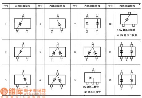
The structure circuit diagram of chip diode is shown as the chart.
The chip diode has many different types such as the rectifier diode, varactor diode, fast recovery diode, switching diode, zener diode, light emitting diode and transient voltage suppression diode. Most models of the chip diodes use the model of leading diode, some manufacturers also have their own requiring model, There is no uniform requirements.
(View)
View full Circuit Diagram | Comments | Reading(1998)
The typical application circuit diagram of LD7208 police car turning ASIC
Published:2011/5/6 3:25:00 Author:Ecco | Keyword: typical application circuit, police car, turning, ASIC
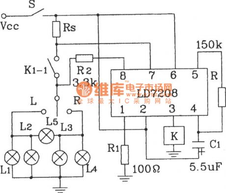
The typical application circuit of LD7208 police car turning ASIC
The main function of the circuit: When normal operation, the lights are in good condition, lights and the monitoring lights of bridge flash at the same time, the flash frequency is 80 times / min. Once the lamp is damaged, then the flashing frequency of monitoring lights will increase twice to show alarm. (View)
View full Circuit Diagram | Comments | Reading(1152)
A Video Games Circuit Diagram
Published:2011/5/6 3:26:00 Author:Ecco | Keyword: Video Games
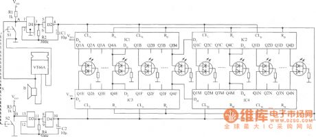
IC1 ~ IC4 are four pairs of CD4051 4-bit shift register; D1 ~ D4 use a CD4011 2 input NAND gate. Color tri-color LED is 2EF302. (View)
View full Circuit Diagram | Comments | Reading(1400)
The clock circuit diagram for racing
Published:2011/5/6 3:25:00 Author:Ecco | Keyword: clock circuit, racing
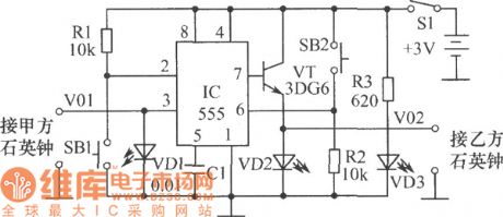
The chart shows the clock for the competition, which is assembled with 555 circuit, with the features of novel circuit, reliable performance, easy making, intuitive interesting. 555 circuit has two categories of bipolar circuit (TTL) and complementary metal oxide semiconductor-type (CMOS) integrated circuit. It is a very broad application IC with only a small amount of external components, it is very easy to form a single stable, bistable, non-stable circuit. The selection of components: IC uses bipolar CD555 time base circuit. VT selects 3DG6 transistor. VD1 ~ VD3 chooses Φ5mm. The clock uses analog quartz.
(View)
View full Circuit Diagram | Comments | Reading(1353)
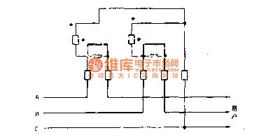
The dual component sine table wiring circuit diagram of three-phase reative energy meter with 60-degree of phase angle differential
Published:2011/5/6 2:41:00 Author:TaoXi | Keyword: dual component, sine table, three-phase, reative energy meter, 60-degree, phase angle differential
The The dual component sine table wiring circuit diagram of three-phase reative energy meter with 60-degree of phase angle differential is as shown:
(View)
View full Circuit Diagram | Comments | Reading(2835)
Digital Servo Integrated Circuit
Published:2011/5/6 1:12:00 Author:Sharon | Keyword: Digital Servo, Integrated
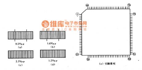
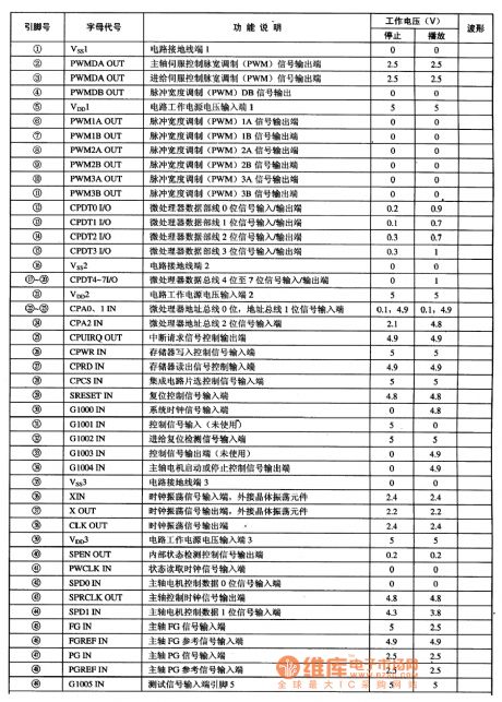
MN67700 IC pin arrangement and related waveforms
MN67700 IC pin functions and data
MV67700 is Panasonic's new DVD digital servo IC, widely used in Panasonic series, Malata, TCL, Konka DVD players.
1. Functions and features: MV67700 integrated circuit includes servo DSP circuit, multiple analog / digital converter circuit or digit/ analog conversion circuit, pulse width modulation circuit, computer interface and multi-purpose interface circuit and the expected error control circuit. It's used for focusing, tracking, and the spindle error signal changing into a digitized operations so as to output servo control signals for servo control of the relevant circuit.2. Pin functions and data: MN67700 IC package applied four flat structure, the pin arrangement shown in Figure (e), and date listed in the table. Letters in Waveform column in the table represent waveforms shown in Figure 8 (a) - (d).
(View)
View full Circuit Diagram | Comments | Reading(878)
uPC1230H2 Amplifier Circuit
Published:2011/5/6 0:16:00 Author:Felicity | Keyword: Amplifier Circuit,
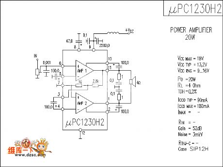
The picture above shows the UPC1230H2 Amplifier Circuit. (View)
View full Circuit Diagram | Comments | Reading(4549)
Differentiation exposure meter circuit
Published:2011/4/29 4:54:00 Author:Nicole | Keyword: exposure meter
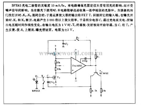
The sensitivity of BPX63 photodiode is 10mA/lx. This circuit can ensure the light and figure location only influenced by the useful light, and it will not beinfluenced by the noise singal. When it is used under gleam, this circuit can fast collect a series of short optical pulse. When the camera shutter is not opened, K1, K2 are closed, the operational amplifier output is connected to its inout terminal by FETT1. when it starts to expose, k1, K2 turn off, the circuit produce more than 3000 times enlargement ratio. Integral capacity C1 is charged by photocurrent, it makes the output voltage linear change with time. When the output voltage is 1V, T3's base-emitter junction starts to turn on. When C1 produces feedback by T3, RL is discontinuous flow, the exposure is ended. The power supply is ±3V. (View)
View full Circuit Diagram | Comments | Reading(704)
Flashlight control toy or sport model circuit
Published:2011/4/29 4:56:00 Author:Nicole | Keyword: flashlight, toy, sport model
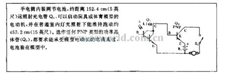
There are two cells in the flashlight, when irradiating the phototube about 152.4cm(5 feet) away, it can start the motor of toy or sport model, and it can keep running about 457.2cm(15 feet) shone in the lights around the indoor. The PNP type power transistor(Q2) requires that it can bear the flowing current of mode motor, the cells are fixed in mode. (View)
View full Circuit Diagram | Comments | Reading(568)
2×15W Power Amplifier Circuit made by IC TDA1521A Hi-Fi Amplifier
Published:2011/5/5 10:00:00 Author:Felicity | Keyword: 2×15W, Power Amplifier, Hi-Fi Amplifier,
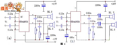
The picture above shows the 2×15W Power Amplifier Circuit Made byIC TDA1521A Hi-Fi Amplifier. (View)
View full Circuit Diagram | Comments | Reading(2631)
Spectacular owl principle circuit diagram
Published:2011/5/5 22:04:00 Author:Ecco | Keyword: Spectacular , owl , principle
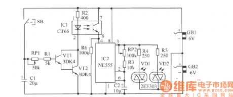
The owl circuit is shown as the chart, starting the reclosing button will make electronic owl's eyes immediately turn between red and green alternately. After a period of delay, the end result is that electronic owl is automatically transferred to rest as work fatigue . Components Selection: IC1 uses CT66 8-pin photocoupler manifold, which has two sets of optical couplers, the practical application only selects one group. IC2 can choose NE555, FD555, 5G555 and other types of time-base integrated circuits. VT1, VT2 select NPN silicon transistors, the available models are: 3DG6, 3DG8, 3DG12, 3DK2, 3DG182, 9013, etc., β can be greater than 50. VD1, VD2 use 2EF303 color light emitting diodes. All resistors used in the circuit choose (1 / 8) W metal film resistors. (View)
View full Circuit Diagram | Comments | Reading(1010)
AC and DC voltage meter wiring method circuit
Published:2011/5/5 21:39:00 Author:TaoXi | Keyword: wiring method, AC, DC, voltage meter
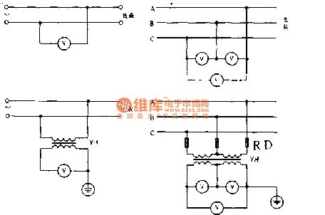
The AC and DC voltage meter wiring method circuit is as shown:
(View)
View full Circuit Diagram | Comments | Reading(678)
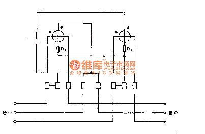
Three-phase reactive electric meter sine meter circuit
Published:2011/5/5 21:35:00 Author:TaoXi | Keyword: Three-phase, reactive electric meter, sine meter
The Three-phase reactive electric meter sine meter circuit is as shown:
(View)
View full Circuit Diagram | Comments | Reading(893)
UM91215A/C microcomputer single chip dialing integrated circuit diagram
Published:2011/5/5 8:46:00 Author:Nicole | Keyword: microcomputer, single chip dialing
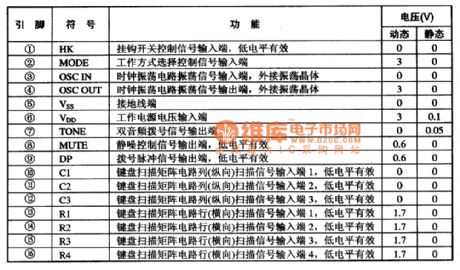
UM91215A, UM91215C are microcomputer single chip dialing integrated circuit, as dialing circuit, it is used in communication equipment.
UM91215A adopts 16-foot dual in-line package, UM91215C adopts 18-foot dual in-line package, the later ① foot is hands free control singal output terminal, (18) foot is hands free control singal input terminal. UM91215A integrated circuit's pin function and data are shown in the excel 1-1.
(View)
View full Circuit Diagram | Comments | Reading(988)
Chip diode usual encapsulation and shape dimension circuit diagram
Published:2011/5/5 21:48:00 Author:Ecco | Keyword: Chip diode, usual , encapsulation , shape , dimension
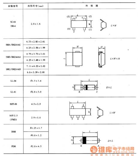
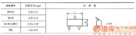
Chip diode usual encapsulation and shape dimension circuit diagram is shown as the chart.
The table lists the ususal package and shape dimensions for reference.
(View)
View full Circuit Diagram | Comments | Reading(635)
| Pages:426/471 At 20421422423424425426427428429430431432433434435436437438439440Under 20 |
Circuit Categories
power supply circuit
Amplifier Circuit
Basic Circuit
LED and Light Circuit
Sensor Circuit
Signal Processing
Electrical Equipment Circuit
Control Circuit
Remote Control Circuit
A/D-D/A Converter Circuit
Audio Circuit
Measuring and Test Circuit
Communication Circuit
Computer-Related Circuit
555 Circuit
Automotive Circuit
Repairing Circuit