
Electrical Equipment Circuit
Index 33
B_Y_DEMODULATOR
Published:2009/7/20 22:21:00 Author:Jessie
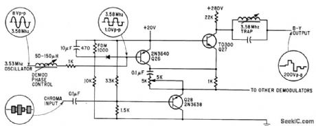
Used in transistorized color tv. R-Y demodulators are identical except for having different demodulation phase angle. –D. Bray, Solid State Makes Debue in Big-Screen Color Tv Electronics, 39:8, p 99-105. (View)
View full Circuit Diagram | Comments | Reading(869)
10_channel_scanning_logic_for_PF_scanner_monitor_receiver
Published:2009/7/20 22:44:00 Author:Jessie
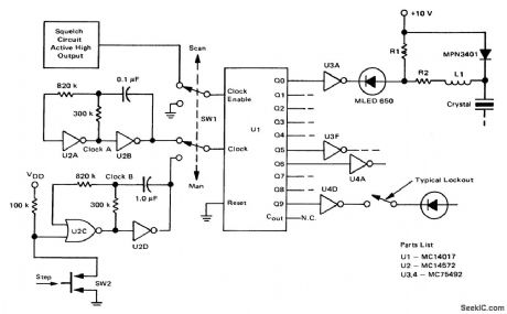
10-channel scanning logic for PF scanner/monitor receiver (courtesy Motorola Semiconductor Products Inc.). (View)
View full Circuit Diagram | Comments | Reading(1144)
SERVO_DRIVE
Published:2009/7/20 22:40:00 Author:Jessie
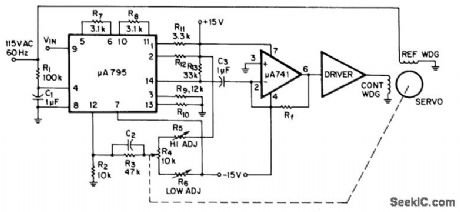
Combination of Fairchild μA795 multiplier and μA741 opamp generates AC error signal for driving two-phase servo-motor. Phase-shifted signal from R1-C1 is applied to input pin 4 of multiplier, DC signal input is applied to pin 9, and servo position signal goes to pin 12. Multiplier takes difference between signals on 9 and 12, multiplies this by signal on pin 4, and feeds resulting sine wave from pin 14 to opamp for amplification and transfer to servo driver. When servomotor action makes voltages on 9 and 12 equal, system is nulled.-Fairchild Linear IC Contest Winners, EEE Magazine, Jan. 1971, p 48-49. (View)
View full Circuit Diagram | Comments | Reading(1672)
27_MHz_to_107_MHz_mixerfor_CB_operation_using_a_TIS148_dual_gate_MOSFET
Published:2009/7/20 22:40:00 Author:Jessie
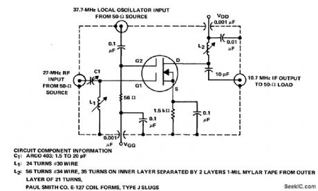
27 MHz to 10.7 MHz mixerfor CB operation using a TIS148 dual-gate MOSFET(courtesy Texas Instruments Incorporated). (View)
View full Circuit Diagram | Comments | Reading(1051)
5_digit_incandescent_display
Published:2009/7/20 22:36:00 Author:Jessie
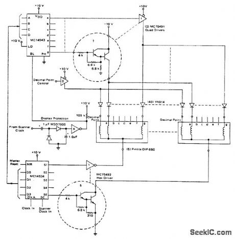
5-digit incandescent display (courtesy Motorola Semiconductor Products Inc.). (View)
View full Circuit Diagram | Comments | Reading(660)
900_MHz_BF_amplifier_using_a_3N225_dual_gate_MOSFET
Published:2009/7/20 22:35:00 Author:Jessie

900 MHz BF amplifier using a 3N225 dual-gate MOSFET. Coils L1 and L2 consist of the leads of the 1 pF and 3 pF capacitors (courtesy Texas Instruments Incorporated). (View)
View full Circuit Diagram | Comments | Reading(764)
12_VDC_DRIVE
Published:2009/7/20 23:05:00 Author:Jessie

Circuit uses 791 power opamp in inverting configuration with gain of 10 for driving size 8 12-VDC servomotor in either direction. Article tells how to calculate heatsink requirements for opamp.-R. J. Apfel, Power Op Amps-Their Innovative Circuits and Pack-aging Provide Designers with More Options, EDN Magazine, Sept. 5, 1977, p 141-144, (View)
View full Circuit Diagram | Comments | Reading(945)
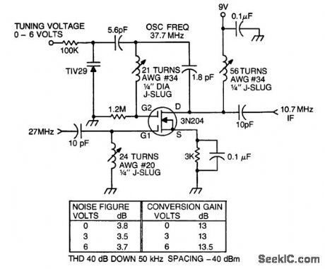
163_MHz_oscillator_for_low_side_injection_in_CB_operation_using_a_TIS148_dualgate_MOSFET
Published:2009/7/20 22:59:00 Author:Jessie
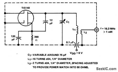
16.3 MHz oscillator for low-side injection in CB operation using a TIS148 dualgate MOSFET(courtesy Texas Instruments Incorporated).
(View)
View full Circuit Diagram | Comments | Reading(656)
105_MHz_to_107_MHz_mixer
Published:2009/7/20 22:58:00 Author:Jessie
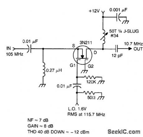
105 MHz to 10.7 MHz mixer (courtesy Texas Instruments Incorporated). (View)
View full Circuit Diagram | Comments | Reading(789)
105_MHz_PF_amplifier_using_a_3N204_dual_gate_MOSFET
Published:2009/7/20 22:56:00 Author:Jessie
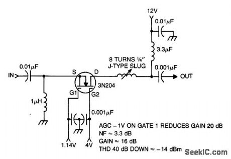
105 MHz PF amplifier using a 3N204 dual-gate MOSFET (courtesy Texas Instruments Incornorated). (View)
View full Circuit Diagram | Comments | Reading(798)
125_MHz_IF_amplifier_using_a_3N225_dual_gate_MOSFET
Published:2009/7/20 23:27:00 Author:Jessie
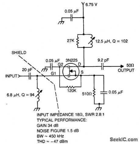
12.5 MHz IF amplifier using a 3N225 dual-gate MOSFET(courtesy Texas Instluments Incorporated). (View)
View full Circuit Diagram | Comments | Reading(699)
27_MHz_autodyne_tuner_using_a_3N204_dual_gate_MOSFET
Published:2009/7/20 23:25:00 Author:Jessie
27 MHz autodyne tuner using a 3N204 dual-gate MOSFET (courtesy Texas Instruments Incorporated). (View)
View full Circuit Diagram | Comments | Reading(1219)
45_MHz_58_MHz_BF_ampllfier_with_tuned_input
Published:2009/7/20 23:22:00 Author:Jessie
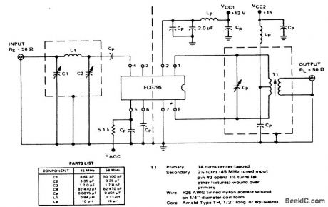
45 MHz/58 MHz BF ampllfier with tuned input.See listing for component values(courtesy GTE Sylvania Incorporated). (View)
View full Circuit Diagram | Comments | Reading(708)
FM_wireless_microphone_using_and_ECG1014_and_ECG1017
Published:2009/7/20 23:19:00 Author:Jessie
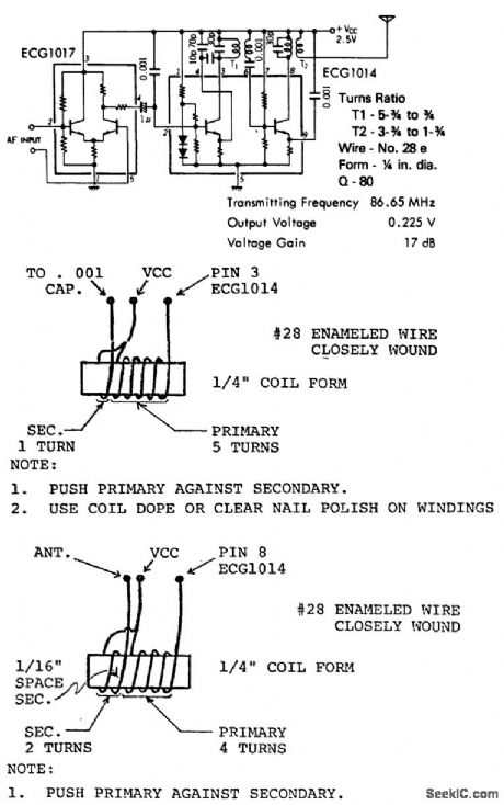
FM wireless microphone using and ECG1014 and ECG1017. Circuit works well up to 250 to 300 feet. For maximum stability cement coil forms to chassis or board. Recommended supply voltage is 4.5 volts using three cells (courtesy GTE Sylvania Incorporated). (View)
View full Circuit Diagram | Comments | Reading(825)
Mltiplier_with_op_amp_level_shift
Published:2009/7/21 1:44:00 Author:Jessie
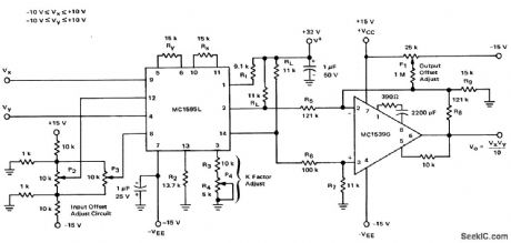
Mltiplier with op amp level shift (courtesy Motorola Semiconductor Products Inc.). (View)
View full Circuit Diagram | Comments | Reading(879)
Arc_tangent_function_from_the_4301_multifunction_chip
Published:2009/7/21 1:37:00 Author:Jessie

Arc tangent function from the 4301 multifunction chip (courtesy Burr-Brown Research Corporation). (View)
View full Circuit Diagram | Comments | Reading(746)
Sine_function_from_the_4301_multifunction_chip
Published:2009/7/21 1:36:00 Author:Jessie
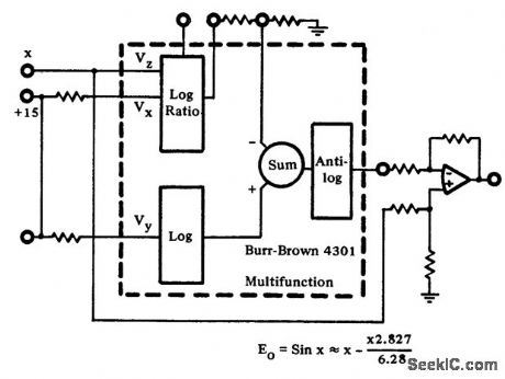
Sine function from the 4301 multifunction chip (courtesy Burr-Brown Research Corporation). (View)
View full Circuit Diagram | Comments | Reading(771)
Square_rooter_circuit_using_the_435_multiplier_divider_chip
Published:2009/7/21 1:35:00 Author:Jessie
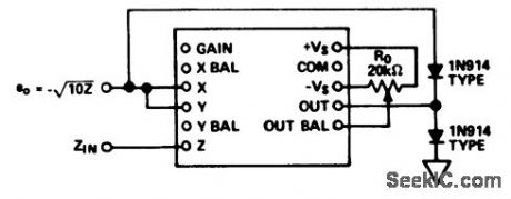
Square rooter circuit using the 435 multiplier/divider chip (courtesy Analog Devices, Inc.). (View)
View full Circuit Diagram | Comments | Reading(711)
Divider_circuit_with_digitally_controlled_gain
Published:2009/7/21 1:34:00 Author:Jessie
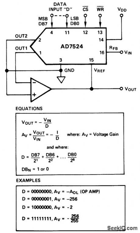
Divider circuit with digitally controlled gain (courtesy Analog Devices, Inc.). (View)
View full Circuit Diagram | Comments | Reading(769)
CAPACITOR_BALANCED_SSB
Published:2009/7/20 23:56:00 Author:Jessie
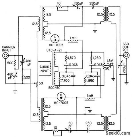
Output varies linearly with input over signal range of 0 to 4.5 V. Undesired sideband is suppressed 26 db at balance.-A. C. Todd, R P. Schuck, and H. M. Sachs, Using Voltage-Variable Capacitors in Modulator Design, Electronics, 34:3, p 56-59. (View)
View full Circuit Diagram | Comments | Reading(840)
| Pages:33/126 At 202122232425262728293031323334353637383940Under 20 |
Circuit Categories
power supply circuit
Amplifier Circuit
Basic Circuit
LED and Light Circuit
Sensor Circuit
Signal Processing
Electrical Equipment Circuit
Control Circuit
Remote Control Circuit
A/D-D/A Converter Circuit
Audio Circuit
Measuring and Test Circuit
Communication Circuit
Computer-Related Circuit
555 Circuit
Automotive Circuit
Repairing Circuit