
Electrical Equipment Circuit
Index 26
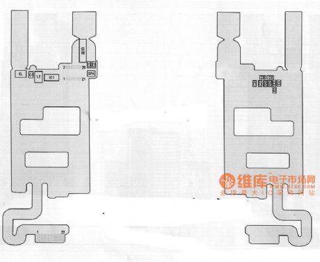
Inspur CU100 mobile phone cable components distribution diagram
Published:2011/8/3 21:46:00 Author:Ecco | Keyword: Inspur, mobile phone , cable components distribution
View full Circuit Diagram | Comments | Reading(822)
ATV_LINE_SAMPLER
Published:2009/7/12 23:14:00 Author:May

This device can be used to recover demodulated video from the output of an ATV transmitter. A small sample of the signal on the antenna feeder is tapped off and detected, and the resultant video is fed to an emitter follower. C1 is chosen for 1 V p-p under normal transmit conditions. This circuit was intended for 440-MHz AM TV signals. It will not work for FM or for 900-MHz or 1300-MHz signals. A striplike directional coupler can be used to sample the RF line without introducing an im-pedance bump.
(View)
View full Circuit Diagram | Comments | Reading(1397)
HEART_SOUND_SIMULATOR
Published:2009/7/16 21:38:00 Author:Jessie
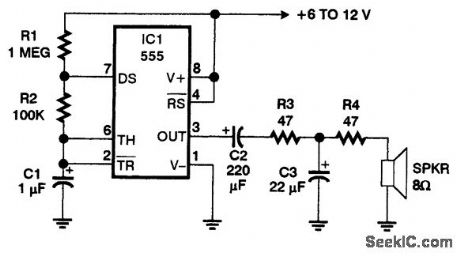
This oscillator circuit imitates the sound of a heartbeat. Use a 4-in or larger speaker to get good bass response. (View)
View full Circuit Diagram | Comments | Reading(1233)
PATHFINDER
Published:2009/7/16 21:37:00 Author:Jessie
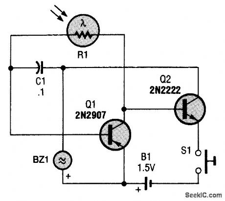
This circuit is little more than a simple two-transistor oscillator (a relaxation type) whose frequency is controlled by a light-dependent resistor (LDR). The oscillator can be built using nearly any NPN and PNP transistor combination desired, and its operation is simple, as its parts count is low. The resistance of R1 and the value of C1 determine the oscillating frequency of the circuit, which varies from a slow tick in darkness (when R1 is about 100,000 Ω) to a high-pitched tone in bright light (when R1 is 1000Ω). The change in frequency is heard through the transducer (BZ1). Power for the circuit is furnished by a single 1.5-V AA battery; because the Pathfinder draws so little power, it will function normally until the battery voltage drops to about 0.9 V. (View)
View full Circuit Diagram | Comments | Reading(1965)
HY8040 Typical Working Principle Circuit
Published:2011/7/18 4:54:00 Author:Felicity | Keyword: HY8040, Typical Working Principle, Circuit
View full Circuit Diagram | Comments | Reading(817)
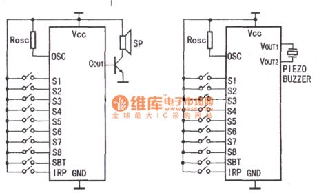
DRINK_AID_FOR_THE_BLIND
Published:2009/7/16 21:31:00 Author:Jessie
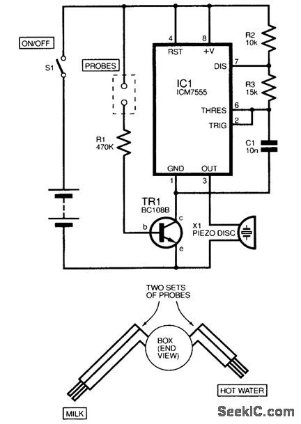
The circuit is an audio oscillator based around IC1, a 555 astable that drives a piezo disk directly. Transistor TRI acts as a switch and will enable the audio oscillator when the two probes detect liquid. By using two sets of probes formed at different lengths (see inset diagram), the audio alarm will activate when enough milk, then enough water, has been added. The circuit is powered by a small 12-V battery (e.g., MN21 type), which should give many years of continuous service because the quiescent current is virtually nil. The device was housed in a small circular plastic box, approximately 4 cm in diameter. The probes were formed from sheathed, thick solid-core copper wires protruding from either side so that the container could clip onto the side of the cup. (View)
View full Circuit Diagram | Comments | Reading(1199)
LOW_RFI_AC_LIMITER
Published:2009/7/17 1:42:00 Author:Jessie
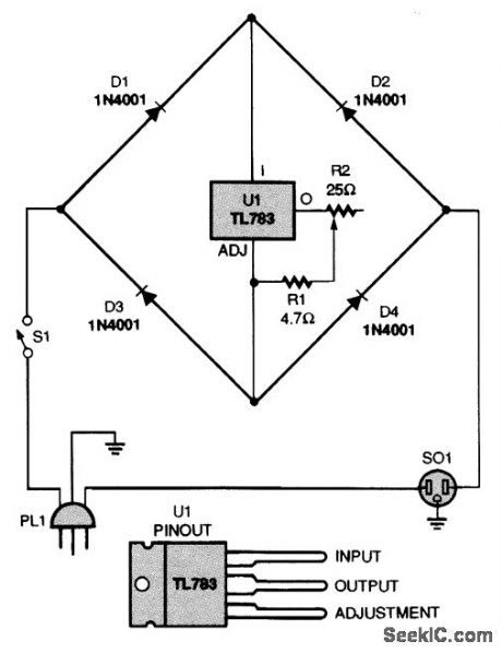
This current limiter will work with any ac device. It does not need a zero-crossing network be-cause it is not based on a triac. Instead, a current-limiting circuit reduces the peaks of the ac waveforms. That is preferable to the action of a triac in a light dimmer, which suddenly turns on and generates significant RE harmonics (even with a zero-crossing network) in all but the fully ON state. (View)
View full Circuit Diagram | Comments | Reading(3982)
80_METER_CW_DIRECT_CONVERSION
Published:2009/7/11 3:23:00 Author:May
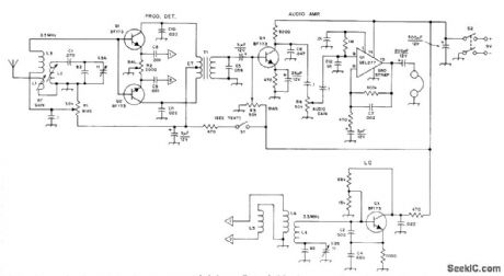
Resonant-dipole antenna feeds directly into balanced product detector that cancels strong interfering local broadcast signals but adds products of mixing with local oscillator that covers 3490-3660 kHz for CW work. R3 is adjusted only once for best performance. Only half of GE GEL277 dual power amplifier is used, for gain of 40 dB. Circuit values make AF amplifier resonate at 1 kHz,with 12dB of attenuation per octave on either side of this center frequency.T1 should be shielded against vertical-sync magnetic fields of TV sets up to 60 feet away.T1 is transistor push-pull output transformer.Use twisted pair for connecting 1-1 and 2-2, to prevent imbalance effects. Article gives construction details for L1-L4.-B. Pasaric, A New Front End for Direct-Conversion Receivers,QST,Oct 1974,p 11-14. (View)
View full Circuit Diagram | Comments | Reading(2176)
SIMPLE_MONOCHROME_TV_PATTERN_GENERATOR
Published:2009/7/11 3:14:00 Author:May
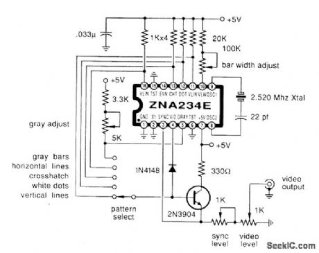
Using a Plessey ZNA234E IC, this generator produces sync, blankin gray bars lines, dots and crosshatch patteflls. (View)
View full Circuit Diagram | Comments | Reading(2127)
TV_LINE_PULSE_EXTRACTOR
Published:2009/7/11 2:38:00 Author:May

This circuit uses a sync-generator chip, a counter, and a decoder to detect the horizontal sync pulse that occurs at the bGginning of line 10 in field 1 of an NTSC television picture. You can use this circuit to compare the time delay between sync signals at various locations, and to determine and correct for any drift between the two master clocks.The output of the LM1881 sync separator is the key to detecting line 10; the odd/even line goes high on the leading edge of the first equalizing pulse in the middle of line 4. Thus, you can use this knowledge to find virtually any other line in the field. This particular circuit locates line 10 of field one. The circuit resets the 74LS161 counter until the odd/even line goes high. Then, 74LS161 counts the positive transitions of the sync signal. After 11 positive transitions, the sync pulse drives pin 4 of the 74LS138 decoder low, and the line-10 sync pulse appears at pin 12 of the decoder. (The circuit counts to 11, as opposed to the 6 you might expect-because the composite sync signal contains more than 1 pulse per line). The counter remains in its maximum-count state until the sync separator causes a reset because Q1 feeds the inverted terminal-count output back to the parallel-enable input. (View)
View full Circuit Diagram | Comments | Reading(1993)
TAPELESS_RECORD_PLAY_DEVICE
Published:2009/7/17 4:00:00 Author:Jessie
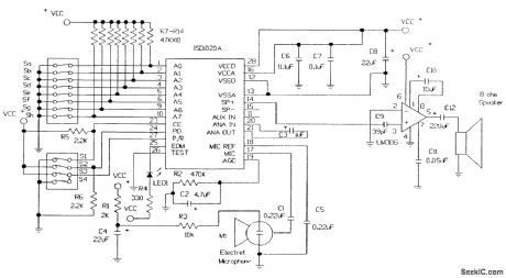
The schematic for a record/play device with an audio power amplifier added is shown.
●A four-section DIP switch is used to activate the Chip enable, Power down, Playback, and Record functions.●An LED detects an end-of-message condition. It remains off during Record or Play and turns on when a message ends.●A three-terminal electret microphone is used for recording.●The only off-board components are the microphone, speaker, and power supply. For optimum sound, the speaker should be baffled (placed in an enclosure). Four 1.5-V AA cells can be used as a power source. (View)
View full Circuit Diagram | Comments | Reading(1562)
TELEPHONE_LINE_IN_USE_INDICATOR
Published:2009/7/10 23:29:00 Author:May
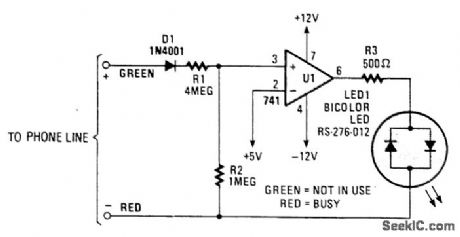
When a telephone line is not in use, about 48 V appears across the line, which drops to about 10 V or less when the line is in use. This circuit switches a bicolor LED as an indicator. (View)
View full Circuit Diagram | Comments | Reading(1134)
REMOTE_RINGER
Published:2009/7/10 23:24:00 Author:May
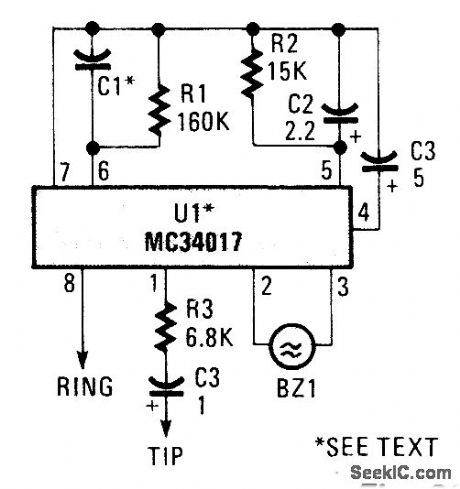
A telephone bell circuit usmg a Motorola MC34017 can be built from a few components. C1 and UI depend on the type of nng required.U1 C1 RingMC34017-1 1 000 pF 1 kHzMC34017-2 500 pF 2 kHZMC34017-3 2 000 pF 500 HzSelect the verslon of MC34017 and C1 from this table. (View)
View full Circuit Diagram | Comments | Reading(996)
TELEPHONE_VISUAL_RING_INDICATOR_1
Published:2009/7/10 23:16:00 Author:May
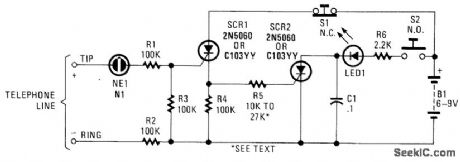
In this circuit, the ringing voltage on a telephone line causes NE-1 to break over, triggering SCR1, which in turn triggers SCR2. If a call has been received, depressing S2 will cause LED1 to light. Depressing S1 resets the circuit. This circuit has the advantage of lower battery drain because LED1 is not left on continuously after a ring signal, but only when S2 is depressed. (View)
View full Circuit Diagram | Comments | Reading(1063)
EXTENSION_PHONE_RINGER
Published:2009/7/10 23:13:00 Author:May
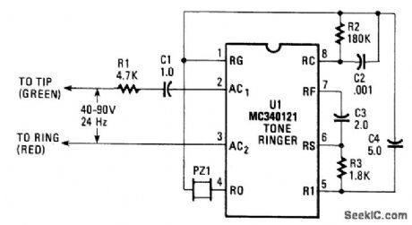
The ac ringing voltage (typically 40 to 90 V at 26 Hz) is rectified by U1, the tone-ringer IC, and is used to drive that IC's internal tone-generator circuitry. The tone-generator IC includes a relaxation oscillator (with a base frequency of 500, 1 000, or 2 000 Hz) and frequency dividers that produce the high- and low-frequency tones, as well as the tone-warble frequency. An on-board amplifier feeds a 20-Vpp signal to the transducer. (View)
View full Circuit Diagram | Comments | Reading(1557)
TELEPHONE_VISUAL_RING_INDICATOR
Published:2009/7/10 22:58:00 Author:May
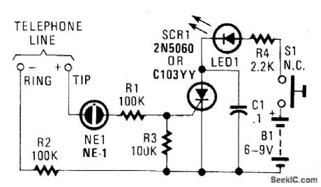
This circuit will indicate the receipt of a call. When the telephone rings,a 100- to 120-V ring signal breaks over NE1, and causes SCR1 to trigger. This causes LED1 to light until the SCR1 is turned off by depressing S1 (View)
View full Circuit Diagram | Comments | Reading(854)
FAHRENHEIT_CENTIG_RADE_LED_THERMOMETER
Published:2009/7/10 22:50:00 Author:May
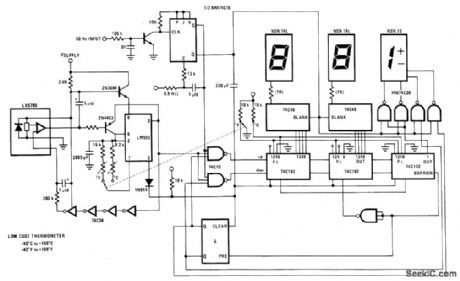

National LX5700 temperature transducer provides input for code conversion circuit driving 3-digit LED display indicating temperature range from -40℃ to +100℃ or -40°F to +199°F under control of ganged switch.- Linear Applications、,Vol. 2, National Semiconductor,Santa Clara.CA.1976,LB-30. (View)
View full Circuit Diagram | Comments | Reading(1132)
THERMOCOUPLE_MULTIPLEXER
Published:2009/7/10 22:46:00 Author:May
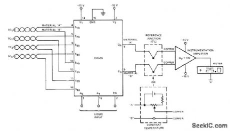
Under control of logic input, DG509 four-channel differential analog multiplexer connects selected one of four thermocouples to instrumentation amplifier driving digital or other readout. To de- room temperature, but this arrangement will be couple sensors from instrumentation amplifier, sensitive to changes in a mbient temperature.-reference junction at 0'0 can be used as shown. Analog Switches and Their Applications, Sil-Altematively, bucking voltage can be set at iconix, Santa Clara, CA, 1976, p 7-77-7-78. (View)
View full Circuit Diagram | Comments | Reading(3621)
TELL_A_BELL
Published:2009/7/10 22:44:00 Author:May
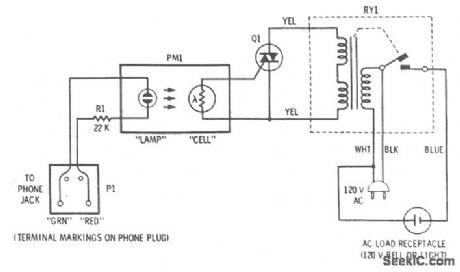
This accessory connects to phone and will activate an attention-getting 120-V bell whenever a ringing voltage appears on the phone line. The four-terminal transducer has a neon bulb close to a photocell, which are both enclosed in a light-tight tube. When the lamp is off, the cell is dark and its resistance is very high. When a ringing voltage appears on the phone line, the neon bulb glows brightly and illuminates the photocell whose resistance then drops to about 1000 Ω. The photocell is in the gate circuit of a triac that will turn on whenever the cell resistance drops. The triac is connected across the switching terminals of the isolation relay. Thus, the relay closes and applies 120 V to the output socket whenever the triac is on. (View)
View full Circuit Diagram | Comments | Reading(1004)
TELEPHONE_AUTO_RECORD
Published:2009/7/10 22:42:00 Author:May
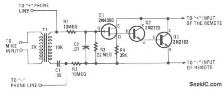
The circuit requires neither a battery nor an ac supply to make it work. Set the recorder to the record position and when the telephone is taken off the hook, the recorder starts to record everything. When the phone is on the hook, the voltage across the phone lines is about 48 Vdc. When it is taken off the hook, the line voltage drops below 10 V. When the line voltage is near 48 V, the FET is biased off and no current can flow through Q2 and Q3. When the receiver is off the hook, the voltage drops, and allows Q1 to conduct. This action turns on Q2, Q3, and the cassette recorder. (View)
View full Circuit Diagram | Comments | Reading(796)
| Pages:26/126 At 202122232425262728293031323334353637383940Under 20 |
Circuit Categories
power supply circuit
Amplifier Circuit
Basic Circuit
LED and Light Circuit
Sensor Circuit
Signal Processing
Electrical Equipment Circuit
Control Circuit
Remote Control Circuit
A/D-D/A Converter Circuit
Audio Circuit
Measuring and Test Circuit
Communication Circuit
Computer-Related Circuit
555 Circuit
Automotive Circuit
Repairing Circuit