
Electrical Equipment Circuit
Index 27
TELEPHONE_INTERCOM
Published:2009/7/10 22:37:00 Author:May
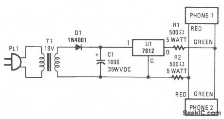
Two telephones can be used as an intercom setup with this simple power-supply arrangement. The 500-Ω resistors maintain line balance. (View)
View full Circuit Diagram | Comments | Reading(0)
TELEPHONE_SILENCER
Published:2009/7/10 22:34:00 Author:May
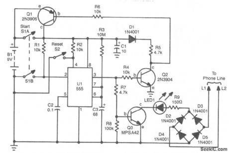
If you are busy and cannot answer or do not wish to answer your phone, this circuit will give a busy signal without you having to leave the phone off the hook. After a predetermined time, the circuit is deactivated. U1 forms an astable multivibrator that can be set for a time up to 10 minutes by values of R3 and C3. When S1A is depressed, U1 starts, and Q1 latches, which powers the circuit. At the end of a time interval determined by R3 and C3, Q2 and Q3 cut off and remove power from the circuit. During the operation, 53 throws a 150-Ω resistor across the phone line, which simulates an off-hook condition. (View)
View full Circuit Diagram | Comments | Reading(1416)
COLOR_FOR_TV_TYPEWRITER
Published:2009/7/10 22:19:00 Author:May

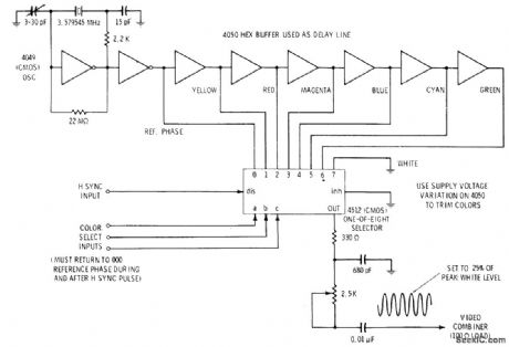
Uses 3.579545-MHz crystal osdllator to drive string of CMOS buffers forming digital delay line. Output delays caused by propagation times in each buffer can be used directly or can be trimmed to specific colors by varying supply voltage. Reference phase and delayed color outputs go to 1-of-8 data selector whose output is determined by code presented digitally to its three color select Iines. Selector drive Iogic must retum to 000 (reference phase) immediately before, during, and for at least several microseconds after each.horizontal sync pulse so set can lock and hold on reference color burst. Sine-wave output chrominance signal is cut down to about one-fourth of maximum video white level.-D. Lancaster, TV Typewriter Cookbook, Howard W Sams, Indianapolis, IN, 1976, p 205-206. (View)
View full Circuit Diagram | Comments | Reading(1878)
TELEPHONE_RINGER
Published:2009/7/10 22:19:00 Author:May

Using an AMI P/N S2561 IC, the circuit shown can be either powered by a battery or the telephone line in use. Output is about 50 mW. (View)
View full Circuit Diagram | Comments | Reading(0)
TV_INTERFACE_FOR_TYPEWRITER
Published:2009/7/10 22:18:00 Author:May

Video input circuitfor black and white transistor TV receiver permits feeding video output of TV typewriter to video driver in set, for producing character or DRIVER game display on TV screen. Use of direct coulpling eliminates shading effect or changes in background level as characters are added.Diodes provide 1.2-V offset in positive direction so in absence of video the video driver is biased to blacker-than-black sync level of 1.2 V. With white video input of 2 V, driver is biased to usual 3.2 V of white level. Hot-chassis TV sets can present shock hazard.-D, Lancaster, TV Typewriter Cookbook, Howard W. Sams, Indianapolis, IN, 1976, p 190. (View)
View full Circuit Diagram | Comments | Reading(1263)
EYEBALL_PRESSURE_GAGE
Published:2009/7/17 4:45:00 Author:Jessie
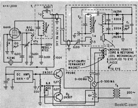
Moving ferrite core in probe deflects in proportion to eyeball pressure and produces signal that is amplified to drive recorder. Plateau of re corded response represents true pressure, which can easily be read independently of peak caused by extra pressure of probe.-R. S. Mackay and E. Marg, Electronic Tono-meter for Glaucoma Diagnosis, Electronics, 33:7, p 115-116. (View)
View full Circuit Diagram | Comments | Reading(750)
125_47O_K_GIVES_125_470_Hz
Published:2009/7/10 22:05:00 Author:May
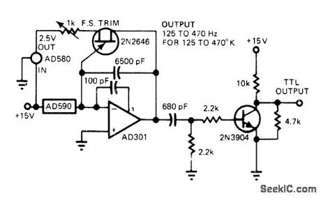
Use of AD590 current-ratioed differential-pair IC temperature transducer gives low parts count for temperature-to-frequency converter. Sensor controls AD301 opamp in relaxation oscillator, with negative-going output ramp being differentiated for driving single-transistor inverter giving TTL output.-J. Williams, Designer's Guide to: Temperature Measurement, EDN Magazine, May 20, 1977, p 71-77. (View)
View full Circuit Diagram | Comments | Reading(829)
HEARTBEAT_TRANSMI_TIER
Published:2009/7/17 4:42:00 Author:Jessie
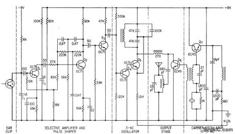
Self-contained device worn by patient transmits his pulse to radio receiver for remote monitoring or recording. Photo-transistor, fed separately, measures changes in light transmitted through earlobe as heart pulses change blood density and volume of lobe.-G. A. Horton and A K.Koroncai, Radio Transmitter for Remote Heartbeat Measurements, Electronics, 33:52, p 54-55. (View)
View full Circuit Diagram | Comments | Reading(750)
TELEMONITOR_FOR_RECORDING_PHONE_CALLS
Published:2009/7/10 21:55:00 Author:May
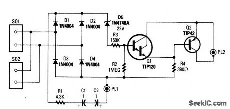
This circuit switches a tape recorder via PL2. When on-hook, D5 conducts, turns on Q1, and cuts off Q2. Ringing voltage will also cause D5 to conduct; C2 and C1 should be rated 150 V or higher. When phone is off-hook, the 10 V or so present on the line will not break down D5, and therefore Q1 is off and Q2 is biased on. PL2 connects to the remote control jack on the tape recorder. Audio is taken from PL1.Caution: Use either a battery tape recorder or an FCC/CSA/UL-approved ac adapter-powered tape recorder. This precaution is to avoid inadvertent 120 Vac on the telephone line. (View)
View full Circuit Diagram | Comments | Reading(859)
TELEPHONE_TOLL_TOTALIZER
Published:2009/7/10 21:44:00 Author:May
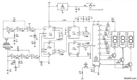
The Telephone loll Totalizer-built around two 4 518 dual synchronous up counters, a 74C925 4-digit counter, a 4 584 hex inverting buffer, and a 4081 quad 2-input AND gate-is fairly simple.Approximate toll charges can be calculated with this counter. It is started when dialing and stopped (manually) on hang-up. It is actually a counter that measures the time you are on the telephone. By calibrating it to the average cost/second of calls (get this from calculations you have done on your monthly phone bill), you can closely estimate your phone bill.The circuit consists of an oscillator running at the 100000 x frequency into the main counter (74C925). Typically, cost of telephone calls is 15 to 25 cents/minute so that the clock frequency (U1) is in the 25- to 40-kHz range. U2 and U4 with gates U3 form a ÷100000 counter. The approximate cost in dollars and cents is read out on the multiplexed display, DISP 1, 2, 3. S2 resets the counter to zero after each use. (View)
View full Circuit Diagram | Comments | Reading(3232)
X_RAY_TUBE_PULSER
Published:2009/7/17 5:24:00 Author:Jessie
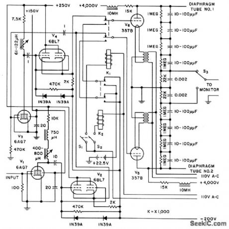
Supplies 3,600 v peakto-peak pulses, swinging from 400 to 4,000 V. Input signal comes from square-wave generator having adjustable duty cycle of 10 to 90% from 35 to 100,000 cps. Uses two pulsating x-ray tubes, each controlled by applying low-voltage square-wave to special diaphragm element. Anode current is maintained constant by switching alternately be. tween tubes. Used for delivering therapeutic dose levels.-E. F. Weller, Roof-Top Target Tubes Pulse X-Rays, Electronics, 31:11,p 138-139. (View)
View full Circuit Diagram | Comments | Reading(2779)
CAMERA_HIGHLIGHT_EQUALIZER
Published:2009/7/20 1:28:00 Author:Jessie
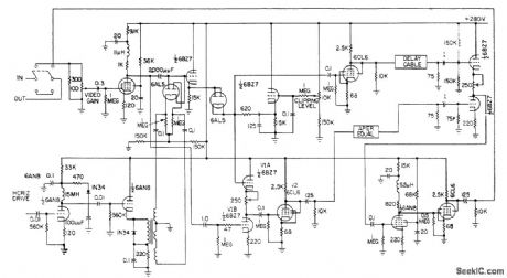
Provides better signal-to-signal noise ratio and improved definition over conventional aperture equalizers covering full brightness range. Since most image orthicon noise is in low light region, improvement is achieved by dividing signal into two parts and equalizing only relatively quiet highlight portion. Complete video signal is amplified and applied to white clipper and to difference amplifier V1-V2. Horizontal drive is also applied to clamp portion of circuit. Video signal is clamped at white clipper, where high-lights are clipped from signal-M. V. Sullivan, Highlight Equalizer Sharpens Tv Pictures, Electronics, 31:3, p 72-74. (View)
View full Circuit Diagram | Comments | Reading(848)
460_KC_F_M_RECEIVER_FOR_WIRELESS_MICRO_PHONE
Published:2009/7/19 22:52:00 Author:Jessie
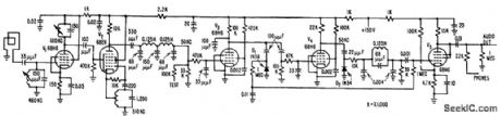
Loop 5 meters square picks up in duction field of four-transmitter and feeds r-f amplifier V1. Operating frequency is converted to 50 kc by V2 and amplified and limited by V3 and V4. Audio signal is recovered after passing through, low-pass filter. Peak audio output is about 0.5 v, enough to feed p-a or speech preamplifier-G. F, Montgomery, Wireless Microphone use F-M Modulation, Electronics, 31:1, p 54-55. (View)
View full Circuit Diagram | Comments | Reading(728)
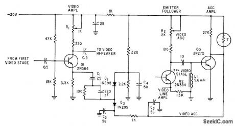
AUTOMATIC_SENSITIVITY_CONTROL_FOR_VIDICON
Published:2009/7/20 1:25:00 Author:Jessie
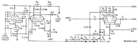
Positive-going blanked video on grid of video amplifier output stage V3A serves to produce negative agc voltage that increases with camera signal, to reduce gain of first video amplifier stage V2A when light input to vidicon camera increases.-P. C.Kidd, Automatic Sensitivity Control for Vidicon TV Camera, Electronics, 35:6, p 52. (View)
View full Circuit Diagram | Comments | Reading(1910)
AUTOMATIC_VIDEO_GAIN_CONTROL
Published:2009/7/20 0:02:00 Author:Jessie
R1 adjusts low-frequency gain of camera video amplifier. Gain control over entire video band is achieved by nonlinear dynamic impedance characteristic of D1 and D2.-D. G. Carreon, Designing Transistorized Television Cameras, Electronics, 33:37, p 72-75. (View)
View full Circuit Diagram | Comments | Reading(881)
SYNC_SIGNAL_DISTRIBUTOR
Published:2009/7/20 0:01:00 Author:Jessie
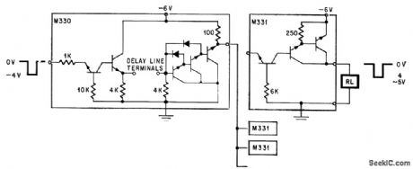
Integrate d circult on two chips distributes synchronizing signal to many television cameras in studio. Delay circuit may be added if needed. Emitter-follower output stage uses Darlington connection for maximum input impedance, while chip for output section (right) uses Darlington to obtain high d-c current gain.-Y. Tarui, Japan Seeks its Own Route lo Improved IC Techniques, Electronics, 38:25, p 90-98. (View)
View full Circuit Diagram | Comments | Reading(992)
15000_V_FOR_UVICON
Published:2009/7/20 Author:Jessie
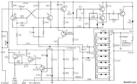
Holds voltage and current output within 1% for 10% in crease or decrease in input. Saturation, related to load current, is sampled at terminals 1 and 2 of output transformer and applied as feedback to control asymmetry of mvbr Q4-Q5, for current control function. Output current is about 15 microamp.-R. N. Riggs, Ultraviolet Space Telescope Will Scan the Stars, Electronics, 35:46, p 37:43.
(View)
View full Circuit Diagram | Comments | Reading(833)
R_F_MODULATOR
Published:2009/7/19 23:59:00 Author:Jessie
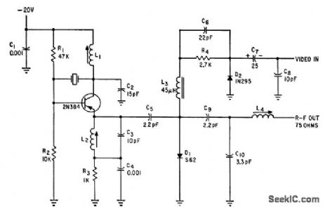
Crystal frequency is half the desired r-f value. L2 and C3 are tuned to second harmonic to give desired r-f channel for tv camera. R-f output is 50 mv into 75-ohm load.-D. G. Carreon, Designing Tran. sistorized Television Cameras, Electronics, 33:37, p 72-75. (View)
View full Circuit Diagram | Comments | Reading(943)
315_KC_CRYSTAL_OSCILLATOR
Published:2009/7/19 23:58:00 Author:Jessie
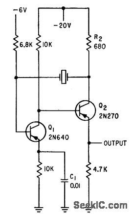
Provides sync signals for tv camera sweeps. Crystal vibrates in lowest-frequency natural mode of long thin bars, resulting in high impedance and difficulty in exciting crystal, and making it necessary to use two transistors in symmetrical collector-coupled mvbr oscillator.-D. G. Cartoon, Designing Transistorized Television Cameras, Electronics, 33:37, p 72-75. (View)
View full Circuit Diagram | Comments | Reading(764)
AIRBORNE_TV_SUNSPOT_CAMERA
Published:2009/7/19 23:57:00 Author:Jessie
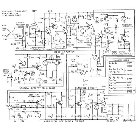
Used with slow-scan iv system for high-altitude solar photography from balloon. Uses 500cps horizontal scan without interlace for 500-line resolution, requiring 200-kc band. width. Video output of camera goes to 2-w commercial 225.7.Mc f-m telemetry transmitter exciting 10.w power stage.-L. E. Flory el al., Television System for Stratoscope I, Electronics, 33:25, p 49-53.
(View)
View full Circuit Diagram | Comments | Reading(1235)
| Pages:27/126 At 202122232425262728293031323334353637383940Under 20 |
Circuit Categories
power supply circuit
Amplifier Circuit
Basic Circuit
LED and Light Circuit
Sensor Circuit
Signal Processing
Electrical Equipment Circuit
Control Circuit
Remote Control Circuit
A/D-D/A Converter Circuit
Audio Circuit
Measuring and Test Circuit
Communication Circuit
Computer-Related Circuit
555 Circuit
Automotive Circuit
Repairing Circuit