
Electrical Equipment Circuit
Index 37
CAMERA_SHUTTER_CONTROL
Published:2009/7/21 4:21:00 Author:Jessie
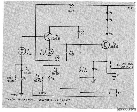
Keeps camera shutter open for predetermined time, to photograph scope as radiation pellet moves past a succession of radiation detector tubes facing conveyor belt. Pellet interrupts light beam to start sweep. RS and C1 control reset time of sweep.-R. L. Nuckolls, Slow Sweep Generator Controls Camera Shutter, Electronics, 38:16, p 82. (View)
View full Circuit Diagram | Comments | Reading(2578)
SINGLE_FRAME_TV_PHOTOGRAPHY_TIMER
Published:2009/7/21 4:19:00 Author:Jessie
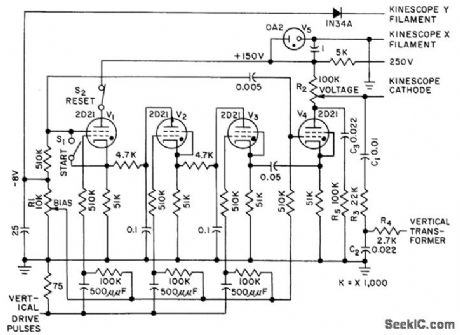
Uses four thyratrons to switch on picture tube for exact 1/30th-sec interval required to complete two interlaced fields and give clean photograph for open-shutter still camera. Vertical drive pulses from tv sync generator provide time-reference triggering. Stabilized high-voltage supply minimizes defocusing.-A. A. Tarnowski and K. G. Lisk, Timer Shutters CRT for Single Frame Photos, Electronics, 31:15, p 83-85. (View)
View full Circuit Diagram | Comments | Reading(698)
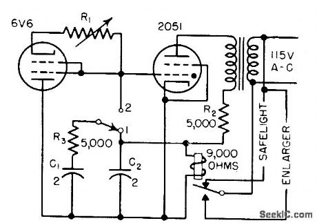
EXPOSURE_INDICATOR_FOR_ENLARGER
Published:2009/7/21 4:17:00 Author:Jessie
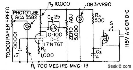
One leg of Wheatstone bridge is unbalanced by light shining on phototube. Sensitivity of circuit is adjusted to match speed of enlarging paper with potentiometer that changes d-c voltage applied to phototube. Meter can be calibrated directly in seconds of exposure -J. Markus and V. Zeluff, Handbook of Industrial Electronic Control Circuits, McGraw-Hill, N.Y., 1956, p 291. (View)
View full Circuit Diagram | Comments | Reading(884)
TV_AFT_system_using_an_EGG1096_14_pin_DIP_with_tab
Published:2009/7/21 4:16:00 Author:Jessie
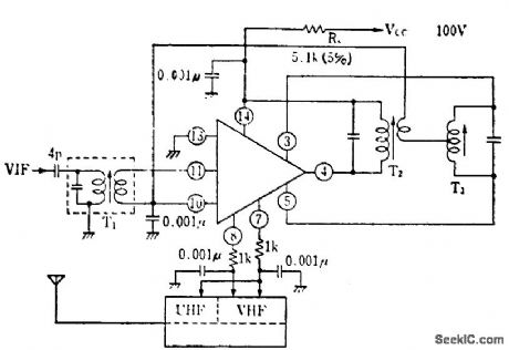
TV AFT system using an EGG1096 14-pin DIP with tab. This type of AFT is for a double-ended system, where both positive and negative correction voltages are required by the VHF tuner. For the UHF tuner one of the correction voltages can be used. Transformers T1, T2 and T3 are selected and tuned for the specific video IF, for example, 45.75 MHz (courtesy GTE Sylvania Incorporated). (View)
View full Circuit Diagram | Comments | Reading(719)
Multiplier_circuit_using_an_AD533
Published:2009/7/21 4:16:00 Author:Jessie

Multiplier circuit using an AD533. With X and Y at zero volts adjust Zo for a zero-volt DC output. With Y at 20 volts peak to peak 50 hertz and X at zero volts adjust Xo for minimum AC output. With X equal to 20 volts peak to peak at 50 hertz and Y at zero volts adjust Yo for minimum AC output. Adjust Zo again for zero volts DC output. With X equal to 10 volts DC and Y equal to 20 volts peak to peak at 50 hertz adjust gain for output equal to YIN (courtesy Analog Devices, Inc.). (View)
View full Circuit Diagram | Comments | Reading(896)
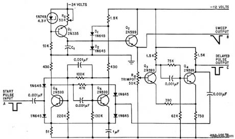
INSTRUMENTATION_CAMERA_TIMER
Published:2009/7/21 4:15:00 Author:Jessie
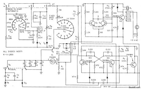
Varies camera exposure rates and durations automatically according to desired program. Triggering rate can be constant and adjustable or variable for selected period between predetermined initial and find rates. Monostable mvbr Q2-Q3 determines length of triggering pulse that operates relay K1.-B. E. Bourne, Variable-Program Triggering Source, Electronics, 33:37, p 76-77. (View)
View full Circuit Diagram | Comments | Reading(936)
EXPOSURE_TIMER
Published:2009/7/21 4:13:00 Author:Jessie
Uses thyratron to stop relay chatter. Gives long time delays with relatively small capacitance. Ordinary volume control covers complete timing range. Circuit is backwards relay, in which coil is energized except during timing interval. Relay pulls in at 10 ma and drops out at 6 ma.-J. Markus and V. Zeluff, Handbook of Industrial Electronic Control Circuits, McGraw-Hill, N.Y., 1956, p 291. (View)
View full Circuit Diagram | Comments | Reading(948)
Divider_circuit_using_an_AD534_multiplier_divider_chip
Published:2009/7/21 4:13:00 Author:Jessie
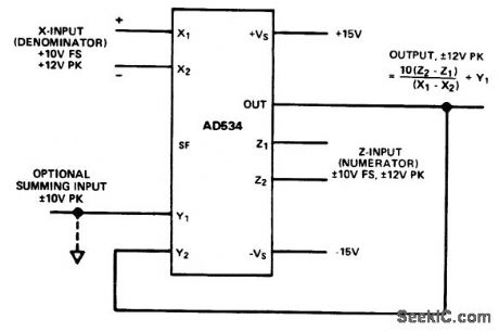
Divider circuit using an AD534 multiplier/divider chip (courtesy Analog Devices, Inc.). (View)
View full Circuit Diagram | Comments | Reading(866)
Complete_RGB_video_output_stageforcolor_TV_using_one_ECG713_chip
Published:2009/7/21 4:12:00 Author:Jessie
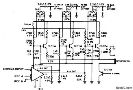
Complete RGB video output stageforcolor TV using one ECG713 chip (courtesy GTE Sytvania Incorporated). (View)
View full Circuit Diagram | Comments | Reading(746)
BOOTSTRAP_TIMER
Published:2009/7/21 4:11:00 Author:Jessie
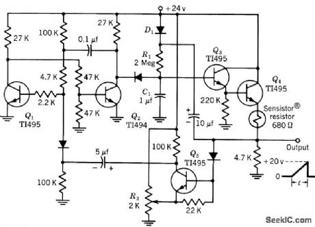
Q1 and Q2 form one-shot mvbr, with Q1 normally on. C1 charges toward 24 V through R1 and D1. Voltage on C1 is followed by Darlington circuit Q3-Q4. Feedback from Q4 to C1 gives nearly linear output voltage rise across emitter resistor of Q4, with length of time cycle varied by controlling emitter vohage of Q5. Overall accuracy of circuit, from -50 to +50℃, is 3%. Can give long time cycles for photographic and acid-bath control. All diodes are 1N2069. -Texas Instruments Inc., Transistor Circuit Design, McGraw-Hill, N.Y., 1963, p 415. (View)
View full Circuit Diagram | Comments | Reading(945)
DATA_RECORDING_CAMERA_TIMER
Published:2009/7/21 3:59:00 Author:Jessie
Controls exposure time and interval between exposures over ranges between 0.1 sec and 2 hours, independently of each other, by changing time constants with C1and C2.-J. G. Fullerton, Bistable Circuit Times Camera Exposures, Electronics, 34:45, p 91. (View)
View full Circuit Diagram | Comments | Reading(819)
Low_frequency_divider_circuit_using_a_PUT
Published:2009/7/21 3:59:00 Author:Jessie
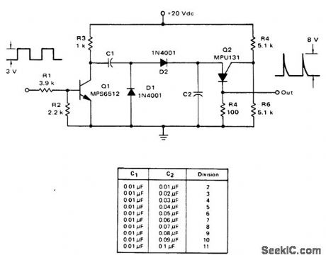
Low-frequency divider circuit using a PUT (courtesy Motorola Semiconductor Products Inc.). (View)
View full Circuit Diagram | Comments | Reading(850)
Square_rooter_circuit_using_an_AD534_multiplier_divider_chip
Published:2009/7/21 3:57:00 Author:Jessie
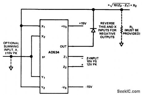
Square rooter circuit using an AD534 multiplier/divider chip (courtesy Analog Devices, Inc.). (View)
View full Circuit Diagram | Comments | Reading(751)
SLAVE_FLASH
Published:2009/7/21 3:57:00 Author:Jessie
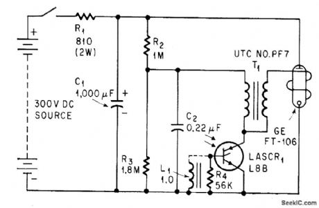
Addition of light-activated scr to ordinary flashgun gives fast-acting slave unit, with response speed of only few microsec to give perfect sync between master and slave. Use of L1 between gate and cathode of LASCR prevents triggering by high-level ambient light because L1 offers low impedance to ambient and high impedance to flash.-E. K. Howell, Light-Activated Switch Expands Uses of Sillicon-Controlled Rectifiers, Electronics, 37:15, p 53-61. (View)
View full Circuit Diagram | Comments | Reading(0)
TV_AFT_AFC_circuit_for_5875_MHz
Published:2009/7/21 3:55:00 Author:Jessie
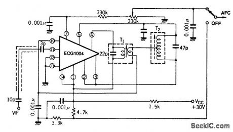
TV AFT/AFC circuit for 58.75 MHz(courtesy GTE Sylvania Incorporated). (View)
View full Circuit Diagram | Comments | Reading(724)
ELECTRONIC_CAMERA_SHUTTER
Published:2009/7/21 3:53:00 Author:Jessie
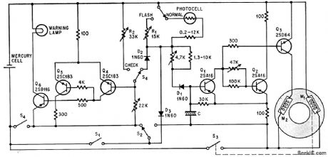
Uses six transistors and photocell to vary both aperture and exposure time automatically according to incident light, from range of 1/30 sec atf/2 to 1/500 sec at 1/16. Transistors are split into two groups, each having a Schmitt trigger and output stage. One group warns photographer when light is insufficient, by turning on warning lamp, and other group drives solenoid that closes shutter at right instant. If light is adequate, depressing shutter button further moves S2 to timing position, and closes 53 to energize solenoid M1 and open shutter to smallest aperture. Mechanical governor then gradually opens camera's combination shutter-iris until M2 snaps it closed under control of Q3.-Open and Shut Case, Electronics, 39:17, p 153-155. (View)
View full Circuit Diagram | Comments | Reading(1147)
TV_FM_sound_system_using_the_ECG712
Published:2009/7/21 3:51:00 Author:Jessie
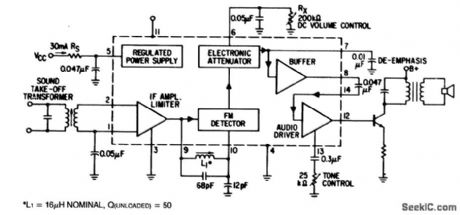
TV FM sound system using the ECG712. The supply terminal can be connected to any supply voltage with a suitable dropping resistor provided that the dissipation rating, 400 mW, is not exceeded since the ECG712 has internal zener regulation. Besides TV, the circuit can be used for FM mobile communications. It also employs DC volume control so no shielding is necessary (courtesy GTE Sylvania Incorporated). (View)
View full Circuit Diagram | Comments | Reading(723)
MOVIE_CAMERA_FRAME_RATE_CHECKER
Published:2009/7/21 3:50:00 Author:Jessie
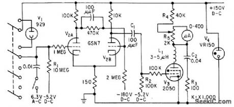
Gives exact frame rate at each instant. Lens is removed for test. Light beam is projected into camera, and reflected back from pressure plate in film gate each time shutter opens. Reflected beam is deflected into phototube that feeds Schmitt trigger. Differentiated output goes to thyratron in circuit of meter that reads frame rates directly from 5 to 64 frames per second. May also be used for checking projectors.-C. Owlett, FrameRate Checker for Motion-Picture Cameras, Electronics, 31 :37, p 88-89. (View)
View full Circuit Diagram | Comments | Reading(867)
True_RMS_circuit_using_the_433_multiplier_divider_chip_and_an_AD741_op_amp
Published:2009/7/21 3:50:00 Author:Jessie
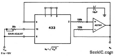
True RMS circuit using the 433 multiplier/divider chip and an AD741 op amp (courtesy Analog Devices, Inc.). (View)
View full Circuit Diagram | Comments | Reading(1308)
Difference_of_the_squares_circuit_using_an_AD532_multiplier_divider
Published:2009/7/21 3:49:00 Author:Jessie
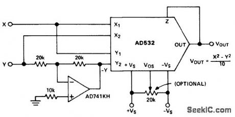
Difference of the squares circuit using an AD532 multiplier/divider. This chip is available as a 10-pin TO-100 or as a 14-pin DIP (courtesy Analog Devices, Inc.). (View)
View full Circuit Diagram | Comments | Reading(678)
| Pages:37/126 At 202122232425262728293031323334353637383940Under 20 |
Circuit Categories
power supply circuit
Amplifier Circuit
Basic Circuit
LED and Light Circuit
Sensor Circuit
Signal Processing
Electrical Equipment Circuit
Control Circuit
Remote Control Circuit
A/D-D/A Converter Circuit
Audio Circuit
Measuring and Test Circuit
Communication Circuit
Computer-Related Circuit
555 Circuit
Automotive Circuit
Repairing Circuit