
Electrical Equipment Circuit
Index 31
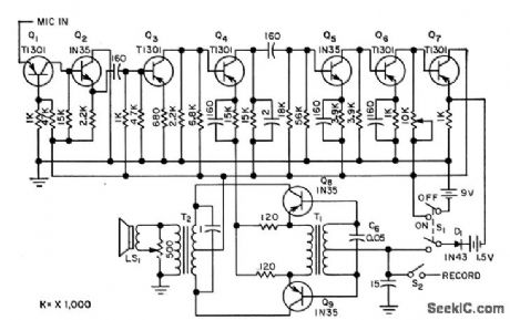
MUSCIE_SIGNAL_AMPLIFIER
Published:2009/7/20 21:12:00 Author:Jessie
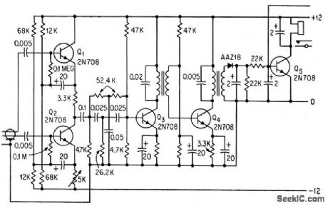
Differential input amplifier Q1-02 accepts myoelectric signals of 10 to 1,000 microvolts from stump muscles of amputee. Stagger-tuned interstage trans-formers for Q3-Q4 give bandwidth of 100to 1,000 cps +or main amplifier that drives integrating detector Q5 that operates relay to control servomotor for artificial hand.-G. W. Horn, Muscle Voltage Moves Artificial Hand, Electronics, 36:41, p 34-36. (View)
View full Circuit Diagram | Comments | Reading(1647)
HEART_RATE_REGULATOR
Published:2009/7/20 21:10:00 Author:Jessie
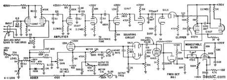
Senses arterial pressure and differentiates pressure signal to eliminate mean pressure and produce required sharp spike at beginning of each pressure pulse. Spikes ore used to control regulator that delivers pulses to vagus nerve that controls muscles of heart.-R. L. Skinner, D. X. Gehmlich, and F. W. Longson, Blood Pressure and Heart Rate Regulator, Electronics, 32:1, p 38-41. (View)
View full Circuit Diagram | Comments | Reading(895)
NERVE_ACTION_POTENTIAL_TRANSMITTER
Published:2009/7/20 21:08:00 Author:Jessie
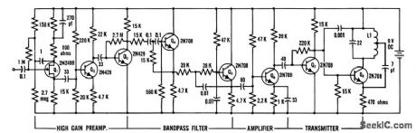
Used in telemetering bioelectric potentials from baroreceptors of blood pressure control system in active awake animals for several days after surgical implantation of electrodes in aorta and carotid arteries. System provides lat frequency response from 1 to 1,200 cps with input impedance of 2.5 meg and input sensitivity of 5 to 500 my. Trans-mining range is 25 feet.-P. Kezdi and W. S.Naylor, Telemetry System to Transmit Baroreceptor Nerve Action Potentials, The American Journal of Medical Electron; 4:4,p 153-155. (View)
View full Circuit Diagram | Comments | Reading(869)
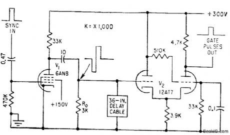
PULSE_CROSS_DISPLAY_GENERATOR
Published:2009/7/20 21:07:00 Author:Jessie
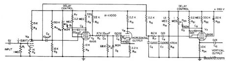
Phantastron circuits delay horizontal and vertical sync pulses, when added to monitor or tv receiver, to provide display for checking operation of tv station sync generator.-H. E. O'Kelley, Pulse-Cross Modification of Tv Receivers, Electronics, 31:9, p 54-55. (View)
View full Circuit Diagram | Comments | Reading(868)
FOETAL_HEART_BEAT_DETECTOR
Published:2009/7/20 21:07:00 Author:Jessie
Amplified 2- to 3-cps signal from foetal heart modulates transistor oscillator operating between 800 and 1,200 cps. Frequency modulation technique overcomes poor low-frequency response of human ear and loudspeaker. A-c coupled stages have large lime constants, to give required low-frequency response.-T. I. Humphreys, Transistor Unit Detects Foetal Heart Sounds, Electronics, 31:17, p 52-54. (View)
View full Circuit Diagram | Comments | Reading(1094)
NONINVERTING_SAMPLE_AND_HOLD
Published:2009/7/20 21:21:00 Author:Jessie
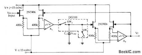
Matched pair of FETs gives high input resistance for analog input signal greater than 1012 ohms, while output resistance of FET pair is under 12K. Opamp A1 acts as buffer and allows C1 to charge rapidly. Use of DG181 analog switches limits leakage current flowing into or out of C1, while SW2 provides fast resetting of capacitor voltage to zero. Similar FET pair and opamp provide output voltage proportional to sampled value.- Analog Switches and Their Applications, Siliconix, Santa Clara, CA, 1976, p 4-7-4-8. (View)
View full Circuit Diagram | Comments | Reading(742)
PRESET_PULSE_COUNTER
Published:2009/7/20 21:19:00 Author:Jessie
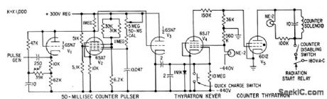
Automatically controls lesion-producing ultrasonic radiation counting up to 99,999. Mechanical counter is actuated by thyratron V5, which is keyed by on by 50-millisec counter pulser driven by leading edge of square wave input pulse.- B. J. Cosman and T.F. Hueter, Instrumentation for Ultrasonic Neurosurgery Electronics,32:20,p 53-57. (View)
View full Circuit Diagram | Comments | Reading(917)
SAMPLE_AND_HOLD_WITH_OFFSET_ADJUSTMENT
Published:2009/7/20 22:15:00 Author:Jessie
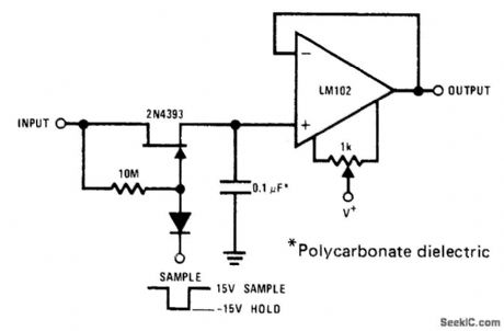
Use of 2N4393 JFET at input of opamp gives simple high-performance circuit having low leakage,Offset is easily adjusted with 1K pot.- FET Databook, National Semiconductor, Santa Clara,CA,1977,p6-26-6-36. (View)
View full Circuit Diagram | Comments | Reading(0)
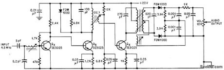
TRANSISTORIZED_COLOR_TV_AUDIO
Published:2009/7/20 22:14:00 Author:Jessie
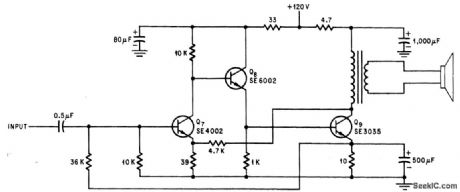
Three-stage class A amplifer provides output of 2 w. Feedback from emitter of Q9 to base of Q7 provides over-all d-c stability.-D. Bray, Solid State Makes Debut in Big-Screen Color Tv, Electronics, 39:8, p 99-105. (View)
View full Circuit Diagram | Comments | Reading(804)
COLOR_BURST_GATING_SIGNAL_GENERATOR
Published:2009/7/20 22:13:00 Author:Jessie
Provides burst gating pulses for operating balanced-diode pate used in studio switching of color tv programs.-J. O. Schroeder, Holding Video levels While Switching Studios, Electronics, 32:22, p 96-98. (View)
View full Circuit Diagram | Comments | Reading(832)
COLOR_DEMODULATOR_1
Published:2009/7/20 22:13:00 Author:Jessie
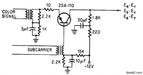
Single demodulator in Japanese 7-inch color tv recovers the three difference signals in sequence by impressing color signal with load subcarrier that is advanced 120°in phase for each line. -Y. Sugihara, H. Ito and A. Horaguchi, From Japan a Startling New Color TV Set, Electronics, 38:11, p 81-94. (View)
View full Circuit Diagram | Comments | Reading(961)
27_MHz_autodyne_tuner_using_a_3N225_dual_gate_MOSFET
Published:2009/7/20 22:12:00 Author:Jessie
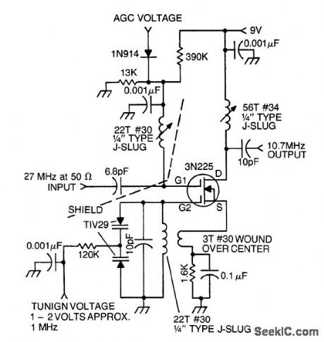
27 MHz autodyne tuner using a 3N225 dual-gate MOSFET (courtesy Texas Instruments Incorporated). (View)
View full Circuit Diagram | Comments | Reading(934)
SAMPLE_HOLD_DISCRIMINATOR
Published:2009/7/20 21:57:00 Author:Jessie
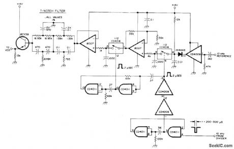
Uses CMOS ICs and CMOS switches to minimize RF noise. Input from 10-kHz reference divider triggers CD4009 gate, and combination of diode and RC circuit produces sawtooth waveform having fast charge and slow discharge. Since input signal pulse may be too narrow, it is widened to 2μs by two-gate mono MVBR for controlling first CD4016 switch. Signal passed from first switch through 8007 opamp to second CD4016 switch is delayed by input of second switch to suppress unwanted spikes, so clean signal is fed through second 8007 opamp to T-notch filter having 10-kHz reference frequency for one leg and 20 kHz for other Ieg. Notch depth can be 60 dB. Filter drives VCO of frequency synthesizer through BCY59 emitter-follower transistor.-U. L. Rohde, Modem Design of Frequency Synthesizers, Ham Radio, July 1976, p10-23. (View)
View full Circuit Diagram | Comments | Reading(1097)
COLOR_BURST_GATED_OSCILLATOR
Published:2009/7/20 21:57:00 Author:Jessie
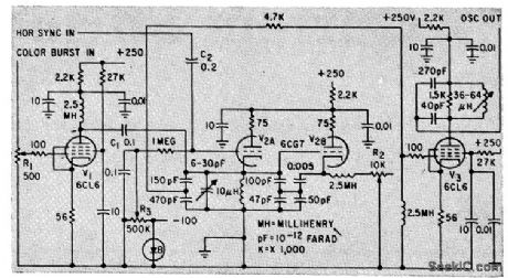
For play-back of color tv recordings on magnetic tape, color burst is removed from composite video signal on tape, amplified by V1, and used to gate 3.58.Mc start-stop oscillator V2 to make this oscillator ring at burst frequency. Regenerated 3.58. Mc signal is am plified by V3 and fed to decoder for demodulating chroma information. -J. Roizen, Magnetic Recording of Color Television, Electronics, 33:1, p 76-79. (View)
View full Circuit Diagram | Comments | Reading(858)
CHROMA_AMPLIFIER
Published:2009/7/20 21:55:00 Author:Jessie
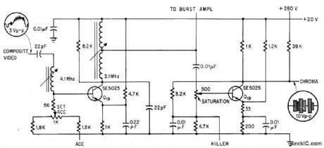
Used in transistorized color tv to provide response slope opposite that of i-f amplifier. Automatic color control signal reduces voltage gain of first stage Q18. Color killer signal cuts off Q19 during monochrome opercation. -D, Bray, Solid State Makes Debut in Big-Screen Color Tv, Electronics, 39;8, p 99-105. (View)
View full Circuit Diagram | Comments | Reading(1499)
COLOR_DEMODULATOR
Published:2009/7/20 21:54:00 Author:Jessie
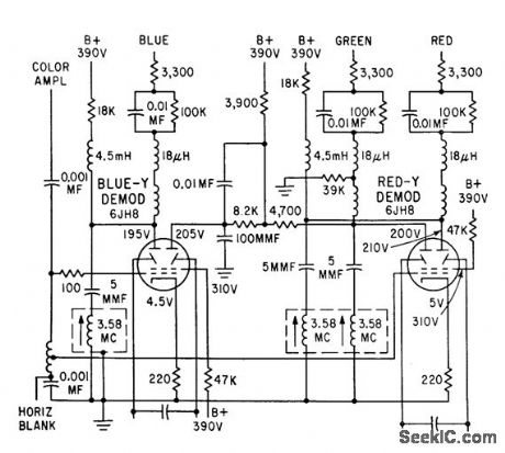
Uses two 6JH8 sheet beam lubes as red and blue luminance demodulators. Balanced outputs of both polarities on plates of tubes eliminate need for additional phase inverter stages to recover green luminance signal-Color Demodulator Uses Beam Switching Tubes, Electronics, 34:36, p 30-31. (View)
View full Circuit Diagram | Comments | Reading(1124)
CHROMA_CONIRQL_AND_COLOR_KILLER
Published:2009/7/20 22:06:00 Author:Jessie
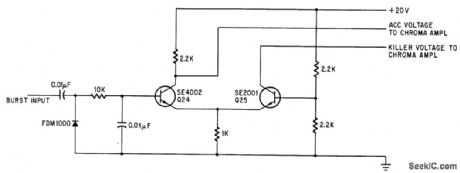
Uses amplifier burst as reference to determine amount of bias on 6rst stage of chromo amplifier. If burst amplifier falls below certain level, color killer voltage cuts off chromo amplifier automatically.-D. Bray, Solid tale Makes Debut in Big-Screen Color Tv, Electronics, 39:8, p 99-105. (View)
View full Circuit Diagram | Comments | Reading(929)
COLOR_SYNC_SEPARATOR
Published:2009/7/20 22:04:00 Author:Jessie
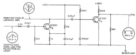
Trcansistorized version eliminates noise from horizontal sync pulses and isolates sync +tom video information. Noise theshold is established by voltage divider in emitter circuit of Q16.-D. Bray, Solid State Makes Debut in Big-Screen Color Tv, Electronics, 39:8, p 99-105.
(View)
View full Circuit Diagram | Comments | Reading(877)
SOUND_I_F_FOR_COLOR_TV
Published:2009/7/20 22:01:00 Author:Jessie
Uses three transislor stages und Foster-Seeley discriminotor to give audio output of 1 v peak to peak. -D. Bray, Solid State Makes Debut in Big Screen Color Tv, Electronics, 39:8, p 99-105.
(View)
View full Circuit Diagram | Comments | Reading(808)
TWO_COLOR_TV
Published:2009/7/20 22:00:00 Author:Jessie

Picture is viewed on half-silvered mirror that combines images of red and green 14-inch picture tubes. Receiver circuits accept standard NTSC color. signal. Chief drawback is narrow angle of vision.-K. Hashimoto, Color TV Based on Land Theory uses Two Single-Gun Tubes, Electronics, 35:38, p 54-55. (View)
View full Circuit Diagram | Comments | Reading(982)
| Pages:31/126 At 202122232425262728293031323334353637383940Under 20 |
Circuit Categories
power supply circuit
Amplifier Circuit
Basic Circuit
LED and Light Circuit
Sensor Circuit
Signal Processing
Electrical Equipment Circuit
Control Circuit
Remote Control Circuit
A/D-D/A Converter Circuit
Audio Circuit
Measuring and Test Circuit
Communication Circuit
Computer-Related Circuit
555 Circuit
Automotive Circuit
Repairing Circuit