
Electrical Equipment Circuit
Index 36
Color_TV_chroma_demodulator_with_RGB_output_matrix
Published:2009/7/21 4:49:00 Author:Jessie
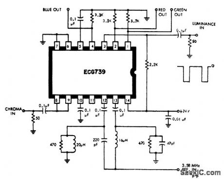
Color TV chroma demodulator with RGB output matrix. By applying a positive going blanking pulse to pin 6, blanking ofthe picture cluing line and frameflyback is achieved (courtesy GTE Sylvania Incorporated). (View)
View full Circuit Diagram | Comments | Reading(1186)
TV_TRANSMITTER
Published:2009/7/8 4:58:00 Author:May
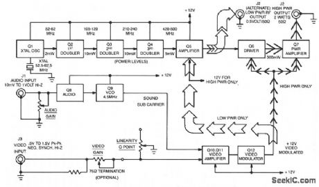
This transmitter is capable of two levels of rf power. For low-power wireless video, like in a house or office, where simultaneous monitoring of program material is desirable without cumbersome hookups, 1-30 mW is available. For longer ranges up to several miles, as in amateur (ham) TV, security, and surveillance purposes, 2 W into a 50-Ω oad is available. (View)
View full Circuit Diagram | Comments | Reading(88)
Divider_circuit_using_the_435_multiplier_divider_chip
Published:2009/7/21 3:32:00 Author:Jessie
Divider circuit using the 435 multiplier/divider chip (courtesy Analog Devices, Inc.). (View)
View full Circuit Diagram | Comments | Reading(659)
Divider_circuit_using_the_433_multiplier_divider_chip
Published:2009/7/21 3:31:00 Author:Jessie
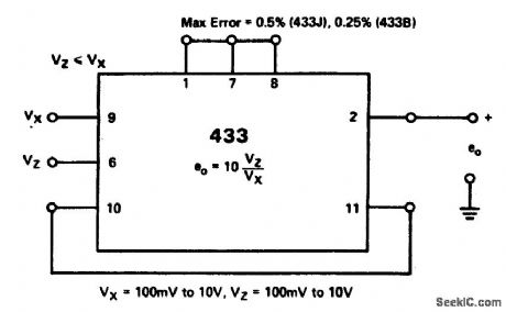
Divider circuit using the 433 multiplier/divider chip (courtesy Analog Devices, Inc.). (View)
View full Circuit Diagram | Comments | Reading(662)
Percentage_computer_using_an_AD534_multiplier_divider_chip
Published:2009/7/21 3:15:00 Author:Jessie

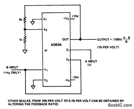
Percentage computer using an AD534 multiplier/divider chip (courtesy Analog Devices, Inc.). (View)
View full Circuit Diagram | Comments | Reading(743)
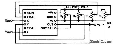
Divider_circuit_using_an_AD532_multiplier_divider_chip
Published:2009/7/21 3:15:00 Author:Jessie
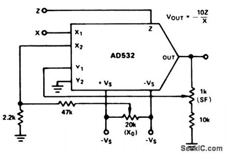
Divider circuit using an AD532 multiplier/divider chip. The AD532 is available as a 10-pin TO-100 or as a 14-pin DIP (courtesy Analog Devices, Inc.). (View)
View full Circuit Diagram | Comments | Reading(894)
TV_video_IF_amplifier_using_an_ECG1128_7_pin_module
Published:2009/7/21 4:10:00 Author:Jessie
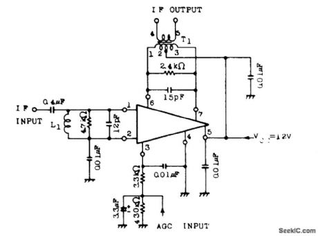
TV video IF amplifier using an ECG1128 7-pin module. Typical power gain is 48 dB. Maximum output voltage is 180 mV (courtesy GTE Sylvania Incorporated). (View)
View full Circuit Diagram | Comments | Reading(631)
PHOTOGRAPHIC_DRYER_CONTROL
Published:2009/7/21 4:09:00 Author:Jessie
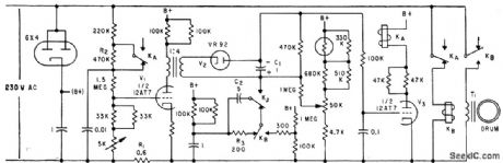
Copper drum, serving as single-turn shorted secondary of transformer, is heated by several thousand amperes of induced current. As drum heats up, transformer primary current decreases. When desired temperature is reached, KA energizes and T1 is disconnected by KB.-D. A. Senior, Temperature Control for Hot Rollers in Industry, Electronics, 32:30, p 40-42. (View)
View full Circuit Diagram | Comments | Reading(807)
Squarer_circuit_using_an_AD533_multiplier_divider_chip
Published:2009/7/21 4:09:00 Author:Jessie
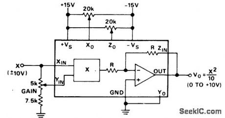
Squarer circuit using an AD533 multiplier/divider chip. With X at zero volts adjust Zo for a zero-volt DC output. With X equal to +10 volts DC adjust gain for +10 volts DC output. Reverse the polarity of X input and adjust Xo to reduce the output error to half its original value and adjust gain to take out the remaining error. Check the output offset with the input grounded. If nonzero repeat the above procedure (courtesy Analog Devices, Inc.). (View)
View full Circuit Diagram | Comments | Reading(1028)
TV_FM_sound_IF_with_tube_type_audio_output_stage
Published:2009/7/21 4:09:00 Author:Jessie
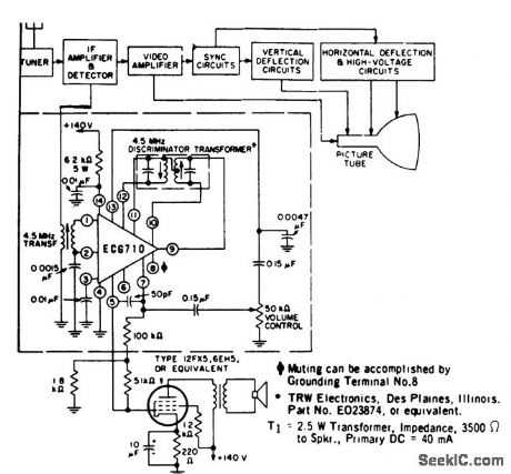
TV FM sound IF with tube-type audio output stage. The ECG710 contains a multistage wide-band amplifier section, a zener-regulated power supply section, and an AF amplifier section (courtesy GTE Sylvania Incorporated). (View)
View full Circuit Diagram | Comments | Reading(720)
MAGNIFICATION_COMPENSATING_DARK_ROOM_TIMER
Published:2009/7/21 4:07:00 Author:Jessie
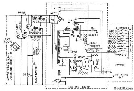
Pushbutton timer provides automatic compensation of exposure time with magnification of negative.-J. Markus and V. Zeluff, Handbook of Industrial Electronic Control Circuits, McGraw-Hill, N.Y., 1956, p 296. (View)
View full Circuit Diagram | Comments | Reading(833)
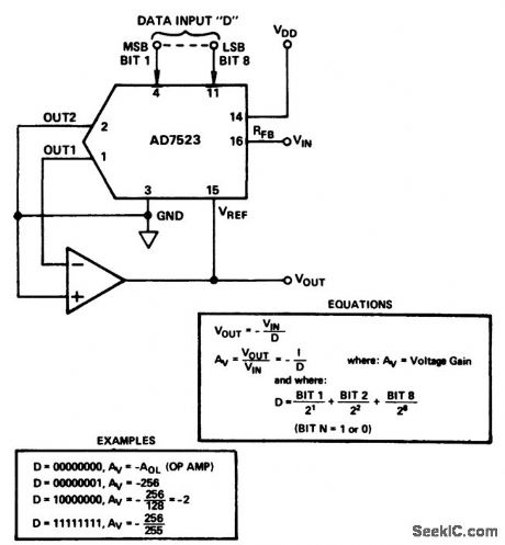
A_D_dividers_using_the_AD7520_18_pin_DIP
Published:2009/7/21 4:07:00 Author:Jessie
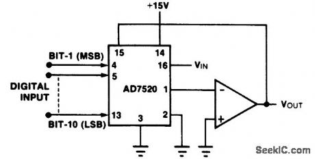
A/D dividers using the AD7520 18-pin DIP. With all bits off the amplifier saturates since division by zero isn’t defined. With the LSB (bit 10) on the gain is 1023. With all bits on the gain is 1 (courtesy Intersil, Inc.). (View)
View full Circuit Diagram | Comments | Reading(777)
TV_sound_channel_with_1_watt_output_using_an_ECG807
Published:2009/7/21 4:06:00 Author:Jessie
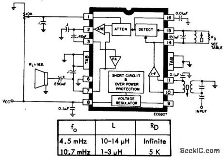
TV sound channel with 1-watt output using an ECG807. The circuit features DC volume control with 70 dB attenuation typical, limiter gain of 70 dB, limiting threshold at 200 μV, automatic thermal shutdown, and audio output short-circuit protection. The circuit will drive 8-, 16- or 32 -ohm speaker loads and provide a true 1-watt output with an 8-ohm load (courtesy GTE Sylvania Incorporated). (View)
View full Circuit Diagram | Comments | Reading(767)
TV_FM_sound_IF_with_transistor_power_output_stage
Published:2009/7/21 4:05:00 Author:Jessie

TV FM sound IF with transistor power output stage. The ECG710 contains a multisection wide-band IF amplifier, a zener-regulated power supply section, and an AF amplifier section (courtesy GTE Sylvania Incorporated). (View)
View full Circuit Diagram | Comments | Reading(793)
Vector_computation_circuit_for_VSUBC_SUBSUP2_SUP__=_VSUBA_SUBSUP2_SUP____VSUBB_SUBSUP2_SUP__using_the_434_multiplier_divider_chip_and_two_AD741_op_amps
Published:2009/7/21 4:05:00 Author:Jessie
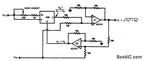
Vector computation circuit for VC2 = VA2 + VB2 using the 434 multiplier/divider chip and two AD741 op amps (courtesy Analog Devices, Inc.). (View)
View full Circuit Diagram | Comments | Reading(604)
KERR_CELL_SHUTTER
Published:2009/7/21 4:04:00 Author:Jessie

High-voltage Kerr-cell pulser and parallel triggering synchronization give 5-nsec exposure, with triggering time jitter less than 1 nsec. Power supply must deliver 350-amp pulse as 35 kv.-S. M. Hauser and H. Quan, Applying the Kerr Cell to Nanosecond Photography, Electronics, 34:33, p 56-59. (View)
View full Circuit Diagram | Comments | Reading(1147)
PHOTOMULTIPLIER_TIMER_FOR_ENLARGER
Published:2009/7/21 4:02:00 Author:Jessie
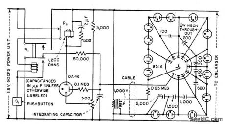
Quartet-watt neon lamps regulate dynode potentials. Graded-capacitor voltage divider across string of neons makes them fire in sequence, to eliminate variations in firing times and increase timing accuracy.-J. Markus and V. Zeluff, Handbook of Industrial Electronic Control Circuits, McGraw-Hill, N.Y., 1956, p 297. (View)
View full Circuit Diagram | Comments | Reading(851)
45_MHz_sound_section_for_TV_using_one_ECG7O6_IC
Published:2009/7/21 4:00:00 Author:Jessie
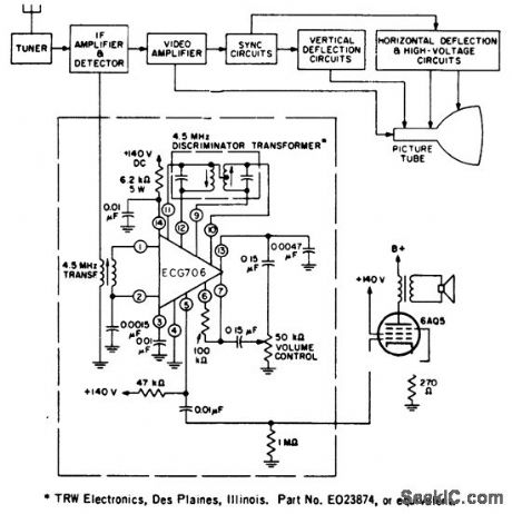
4.5 MHz sound section for TV using one ECG706 IC.The chip contains a wide-band IF amplifier-limiter section,an FM detector stage,a zener regulated power Supply section,and an audio amplifier section specifically designed todrive a 6AQ5(courtesy GTE Sylvania Incorporated). (View)
View full Circuit Diagram | Comments | Reading(1593)
Square_rooter_using_an_AD533_multiplier_divider_chip
Published:2009/7/21 4:23:00 Author:Jessie
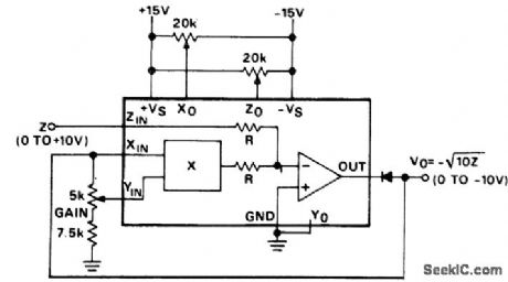
Square rooter using an AD533 multiplier/divider chip. With Z equal to +0.1 volt DC adjust ZO for a-1.0 volt DC output. With Z equal to +10.0 volts DC adjust gain for-10.0 volts DC output.With Z equal to +2.0 volts DC adjust Xo for a -4.47±0.1 volt DC output (courtesy Analog Devices,Inc.). (View)
View full Circuit Diagram | Comments | Reading(753)
Divider_circuit_with_digitally_controlled_gain_1
Published:2009/7/21 4:22:00 Author:Jessie
Divider circuit with digitally controlled gain (courtesy Analog Devices, Inc.). (View)
View full Circuit Diagram | Comments | Reading(695)
| Pages:36/126 At 202122232425262728293031323334353637383940Under 20 |
Circuit Categories
power supply circuit
Amplifier Circuit
Basic Circuit
LED and Light Circuit
Sensor Circuit
Signal Processing
Electrical Equipment Circuit
Control Circuit
Remote Control Circuit
A/D-D/A Converter Circuit
Audio Circuit
Measuring and Test Circuit
Communication Circuit
Computer-Related Circuit
555 Circuit
Automotive Circuit
Repairing Circuit