
Electrical Equipment Circuit
Index 38
Color_TV_358_MHz_crystal_oscillator_using_a_dual_gate_MOSFET_
Published:2009/7/21 5:28:00 Author:Jessie
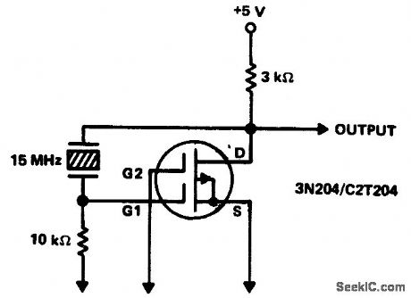
Color TV 3.58 MHz crystal oscillator using a dual-gate MOSFET (courtesy Texas Instruments Incorporated). (View)
View full Circuit Diagram | Comments | Reading(3664)
TV_video_signal_processor_circuit
Published:2009/7/21 5:27:00 Author:Jessie
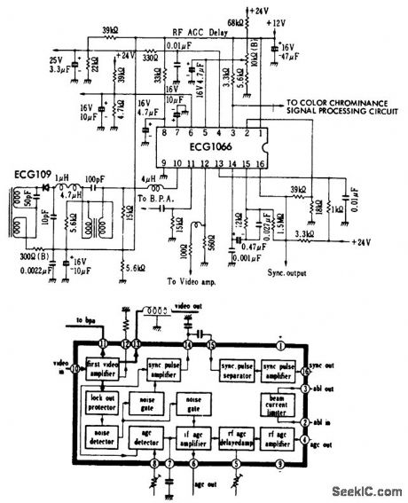
TV video signal processor circuit. The ECG1066 is a 16-pin DIP (courtesy GTE Sylvania Incorporated). (View)
View full Circuit Diagram | Comments | Reading(771)
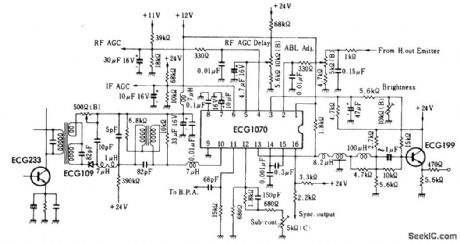
The_ECG1070_16_pin_DiP_
Published:2009/7/21 5:24:00 Author:Jessie
The ECG1070 16-pin DiP (courtesy GTE Sylvania Incorporated). (View)
View full Circuit Diagram | Comments | Reading(750)
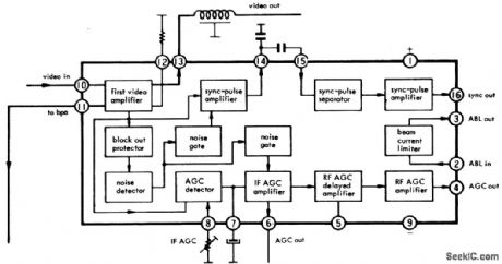
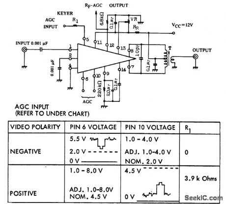
TV_video_signal_processor
Published:2009/7/21 5:23:00 Author:Jessie
TV video signal processor. The ECG 1070 is a 16-pin DIP (courtesy GTE Sylvania Incorporated). (View)
View full Circuit Diagram | Comments | Reading(723)
Linear_TV_IF_amplifier_using_an_ECG_1080_chip
Published:2009/7/21 5:08:00 Author:Jessie
Linear TV IF amplifier using an ECG 1080 chip, which provides 46 dB powergain. Transformer T is 0.32 mm enamel wire with a center-tapped primary of eight tums close wound. The secondary is one tum of the same wire. The coil form diameter is 5.5 mm (courtesy GTE Sylvania Incorporated). (View)
View full Circuit Diagram | Comments | Reading(775)
Color_TV_chroma_demodulator_with_direct_output
Published:2009/7/21 5:07:00 Author:Jessie
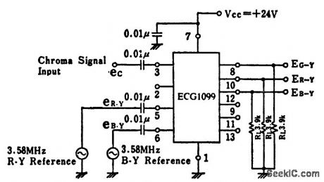
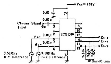
Color TV chroma demodulator with direct output. The ECG1099 is a 14-pinDIP with tab,R-Y,B-Y, and G-Y output voltages are 12 volts,3.8 volts,and 1 volt peak to peak,respectively (courtesy GTE Sylvanic Incorporated) (View)
View full Circuit Diagram | Comments | Reading(898)
Complete_TV_vertical_circuit_with_AFC_for_90_decree_20_inch_receivers
Published:2009/7/21 5:00:00 Author:Jessie

Complete TV vertical circuit with AFC for 90-decree 20-inch receivers (courtesy GTE Sylvania Incorporated). (View)
View full Circuit Diagram | Comments | Reading(792)
65_KV_TWIN_TRIODE_A_F_OSCILLATOR_CRT_SUPPLY
Published:2009/7/21 5:00:00 Author:Jessie
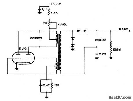
Oscillator develops square wove because of saturable square-loop core materical of transformer. Diodes eliminate extra load placed on oscillator by high-vacuum rectifier tube filaments. –NBS, Handbook Preferred Circuits Navy Aeronautical Electronic Equipment, Vol. 1, Electron Tube Circuits, 1963, p N14-5. (View)
View full Circuit Diagram | Comments | Reading(705)
TV_video_IF_amplifier_and_detector_using_two_8_pin_DIPs
Published:2009/7/21 4:58:00 Author:Jessie
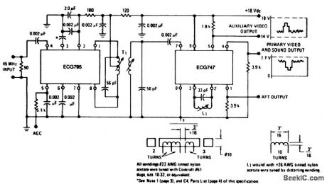
TV video IF amplifier and detector using two 8-pin DIPs.Powergain is as fallows∶60 dB at 45 MHz(pin 3 open), 56 dB at 58 MHz(pin 3 open),61 dB at 45 MHz(pin 3 bypassed),and 59 dB at 58 MHz(pin 3 bypassed).AGC range is 80 dB from DC to 45 MHz,C4 should be 0.002 μF at 45 MHz(courtesy GTE Sylvania Incorporated). (View)
View full Circuit Diagram | Comments | Reading(715)
MODULATOR
Published:2009/7/8 4:33:00 Author:May
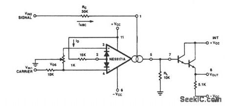
Because the transconductance of an operational transconductance amplifier is directly proportional to IABC, the amplification of a signal can be controlled easily. The output current is the product from transcon-ductance X input voltage. The circuit is effective up to approximately 200 kHz. Modulation of 99% is easy to achieve. (View)
View full Circuit Diagram | Comments | Reading(909)
Color_TV_chroma_demodulator_with_level_shifted_output
Published:2009/7/21 5:21:00 Author:Jessie
Color TV chroma demodulator with level-shifted output. The ECG1099 is a 14-pin DiP with tab (courtesy GTE Sylvania Incorporated). (View)
View full Circuit Diagram | Comments | Reading(777)
Remote_control_receiver_for_TV
Published:2009/7/21 5:20:00 Author:Jessie
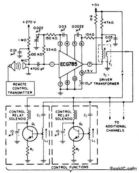
Remote control receiver for TV. Use ECG103 As for the relay drivers. Select the coils and transformers for the desired frequency. The ECG785 has a voltage gain of 129 dB at 40 kHz with the three internal amplifiers in cascade (courtesy GTE Sylvania Incorporated). (View)
View full Circuit Diagram | Comments | Reading(1001)
TV_low_level_video_detector
Published:2009/7/21 5:18:00 Author:Jessie
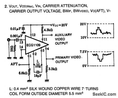
TV low-level video detector. Typical voltage output is 7.5 volts peak to peak. The 14-pin DIP contains a double balanced detector circuit (courtesy GTE Sylvania Incorporated). (View)
View full Circuit Diagram | Comments | Reading(1392)
Color_TV_chroma_amplifier_demodulator_using_an_ECG791_16_pin_DIP
Published:2009/7/21 5:17:00 Author:Jessie
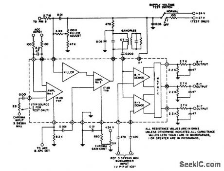
Color TV chroma amplifier/demodulator using an ECG791 16-pin DIP. The circuit features shotl-circuit protection, ACC, and color killer. Typical sensitivity of chroma input is 10 mV RMS with a 50 mV sensitivity for amplifier 2 at pin 4 (courtesy GTE Sylvania Incorporated). (View)
View full Circuit Diagram | Comments | Reading(1340)
Color_TV_subcarrier_generator_uslng_an_ECG1105_16_pin_DIP
Published:2009/7/21 5:10:00 Author:Jessie
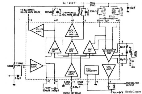
Color TV subcarrier generator uslng an ECG1105 16-pin DIP.The ECG1105 consists of a keyed APC,an ACC,a killer detector amplifier,a burst amplifierand a subcarrier amplitier(courtesy GTE Sytvania Incorporated). (View)
View full Circuit Diagram | Comments | Reading(768)
10_channel_with_thumbwheel_program_mable_priority_logic_for_scanner_monitor_receiver
Published:2009/7/21 6:02:00 Author:Jessie
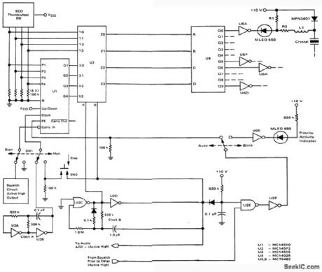
10-channel with thumbwheel-program mable-priority logic for scanner/monitor receiver (courtesy Motorola Semiconductor Products Inc.). (View)
View full Circuit Diagram | Comments | Reading(1135)
9_channel_plus_fixed_priority_cha_nnel_logic_for_PF_scanner_monitor_receiver
Published:2009/7/21 5:58:00 Author:Jessie
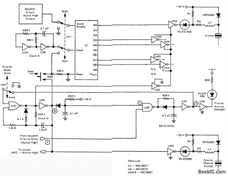
9-channel plus fixed-priority-cha nnel logic for PF scanner/monitor receiver (courtesy Motorola Semiconductor Products Inc.). (View)
View full Circuit Diagram | Comments | Reading(742)
TV_video_IF_output_and_detector_with_AFT_and_sound_take_off_output
Published:2009/7/21 7:35:00 Author:Jessie
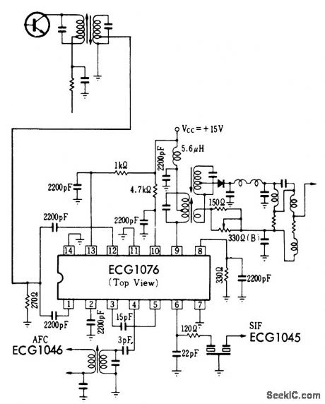
TV video IF output and detector with AFT and sound take-off output. All coils and transformers are standard and can be purchased at a local electronic parts jobber (Merit or Miller components). Sound output at 4.5 MHz is typically 300 mV PMS. AFT output is typically 210 mV PMS at atest frequency of 57 MHz. Typical voltage gain for the video IF is 36 dB (courtesy GTE Sylvania Incorporated). (View)
View full Circuit Diagram | Comments | Reading(798)
45_MHz_TV_sound_channel_with_audio_output_stages
Published:2009/7/21 7:11:00 Author:Jessie
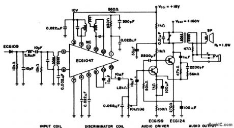
4.5 MHz TV sound channel with audio output stages. The ECG1047 has a three-stage differential amplifier for the IF amplifier section, a ratio detector and first and second audio amplifiers. The IF transformer, ratio detector coil and audio output transformer are standard and can be purchased at Radio Shack. This circuit provides 1.5 watts of audio power into an 8-ohm load (courtesy GTE Sylvania Incorporated). (View)
View full Circuit Diagram | Comments | Reading(1616)
Color_TV_chroma_signal_processor
Published:2009/7/21 6:21:00 Author:Jessie
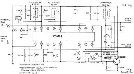
Color TV chroma signal processor. The ECG728 provides subcarrier regeneration and total chroma signal processing prior to demodulation. The coils of the chroma amplifier and bandpass amplifier are stagger-tuned to provide a com-bined typical bandpass of 3.08 to 4.08 MHz. A burst separator amplifier injects the burst signal into the 3.58 MHz oscillator. The ACC detector and killer detector sense the burst level or absence of burst, respectively, by monitoring the osoil-lator's response to the burst injection level. The thresholdsfor the ACC and killer are independently adjusted by resistors R2 and R1 at terminals 9 and 4. The chroma input is at pin 14 and the oscillator output is at pin 8.Pin 6 is a zener diode for use as a regulated voltage reference at 11.9 volts (courtesy GTE Sylvania Incorporated). (View)
View full Circuit Diagram | Comments | Reading(904)
| Pages:38/126 At 202122232425262728293031323334353637383940Under 20 |
Circuit Categories
power supply circuit
Amplifier Circuit
Basic Circuit
LED and Light Circuit
Sensor Circuit
Signal Processing
Electrical Equipment Circuit
Control Circuit
Remote Control Circuit
A/D-D/A Converter Circuit
Audio Circuit
Measuring and Test Circuit
Communication Circuit
Computer-Related Circuit
555 Circuit
Automotive Circuit
Repairing Circuit