
Electrical Equipment Circuit
Index 25
TEMPERATURE_ADAPTER_FOR_DVM
Published:2009/7/14 4:18:00 Author:May
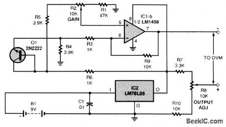
A schematic for the temperature adapter is shown. The circuit outputs 0.01 V/°F. To determine temperature, you ignore the decimal point in the display, and the temperature readout is to the tenth of a degree. For example, if the temperature in a room is 75.5°, your DMM would read +0.755 V. The voltage input for op amp IC1 is obtained from a transistor Q1 used as a diode in this application. The linear voltage drop is measured and used to indicate temperature. The low-power regulator LM78L05 (IC2) provides a fixed 5-V source for the circuit. The voltage drop across Q1 is detected and amplified by IC1, an LM1458 op amp. The output of IC1 is then fed to the input terminals of a DMM. Put the positive lead of a voltmeter on pin 7 of IC1, and the negative lead on ground. Adjust R2 for a reading of 2.5 to 3 V. Connect the output of the adapter circuit to a voltmeter set to the 2-V dc scale. Adjust R8 so that the multimeter reads the same as a stabilized thermometer in the same vicinity as the temperature probe (ignore the decimal point). (View)
View full Circuit Diagram | Comments | Reading(1305)
LOGAMP_WITH_OFFSET_ADJUSTMENT
Published:2009/7/14 3:44:00 Author:May
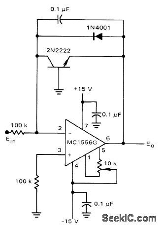
Motorola MC1556G opamp provides accurate operation down to millivolt input levels without bias current compensation. Input offset is adiusted with 10K pot, 0.1-μF capacitor is required actoss feedback transistot to reduce AC gain.Diode protects transistor from polarity reversal of input voltage. Power supplies should be bypassed as close as possible to amplifier socket.Positive input voltage gives negative output voltage. IC includes output short-circuit protection.-K. Huehne, Transistor Logarithmic Conversion Using an Integrated Operational Amplifier, Motorola, Phoenix, AZ, 1971, AN-261A, p 3. (View)
View full Circuit Diagram | Comments | Reading(1056)
UJT_MEIRONOME
Published:2009/7/14 3:44:00 Author:May
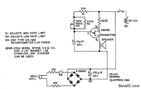
Rate is adjustable from 40 (low largo) to 220(high presto) beats per minute.- Transistor Manual, Seventh Edition, General Electric Co., 1964, p 379. (View)
View full Circuit Diagram | Comments | Reading(1073)
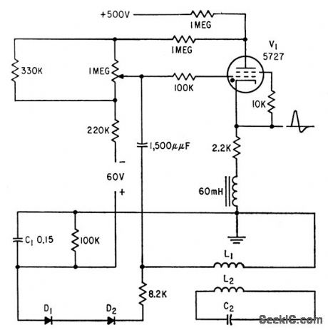
PERCUSSION_OR_ELECTRONIC_MUSIC
Published:2009/7/14 3:43:00 Author:May
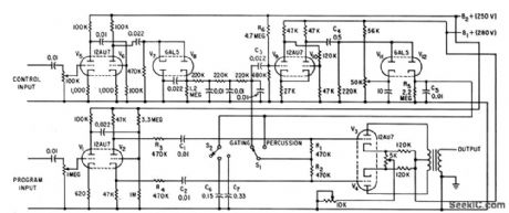
Provides congruent envelope shaping and coincident percussive envelope shaping of synthesized program material. One input accepts control signal, while other accepts material requiring envelope shaping.-H. Bode, Sound Synthesizer Creates New Musical Effects, Electronics, 34:48, p 33-37. (View)
View full Circuit Diagram | Comments | Reading(831)
ORGAN_VOICING_PANEL
Published:2009/7/14 3:41:00 Author:May
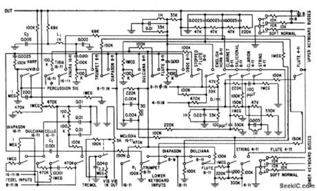
Contains formant filters that transform sawtooth generator signals into waveforms of various instruments. 19 different tone colors or timbres are available, ranging from sharp strings and reeds to bland flutes and pipelike diapasons. Filters are interlocked to produce composite effects.-R. H. Dorf, Electronic Organ Uses Neon Tone Generators, Electronics, 31 ;35,p 36-41. (View)
View full Circuit Diagram | Comments | Reading(1754)
HYDROGEN_THYRATRON_INDUCTION_HEATER
Published:2009/7/14 3:32:00 Author:May
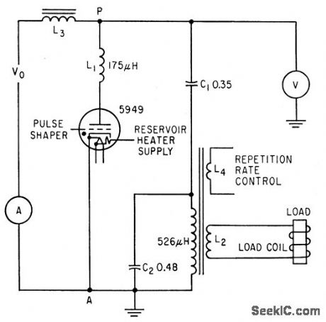
Thyratron acts as high-speed switch, much like spark-gap oscillator, to produce damped oscillations in tank circuit L2-C2.Output frequency is 10 to 14 kc, depending on load. Peak thyratron current is about 340 amp when Vo is 10 kv. Repetition rate depends on maximum average current, and is 124 cps for 0.5 amp. L3 is 0.32 h.-H. L. Van Der Horst, How Radar Techniques Improve Induction Heating, Electronics, 32:7, p 51-55. (View)
View full Circuit Diagram | Comments | Reading(2805)
TELEPHONE_LINE_SIMULATOR
Published:2009/7/14 3:23:00 Author:May

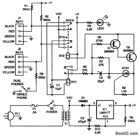
When both handsets are on-hook, resistors R1 and R2 supply power to them. When both hand-sets are off-hook, they transmit and receive their own audio. All the TCB does is supply power to them through R1 and R2. If switch S1 is closed, resistor R6 simulates a telephone being plugged into J2, permitting the testing of only one telephone. Now consider the situation where one handset is on-hook and one is off-hook. That causes the on-hook line to go to 24 Vdc and the off-hook line to go to 7 Vdc. The coil of relay RY1 is connected across the two telephone lines, and the voltage difference between the two lines energizes it. When the contacts of RY1 are closed, C2 charges through R4; it takes about 1 second for C2 to charge to 12 Vdc. The 12 Vdc across C2 causes a voltage-controlled switch consisting of R5, Q1, Q2, SCR1, and R8 to close, thus energizing RY2. When RY2 is energized, RY1 is removed from the circuit and a 60-Hz, 37-V p-p sine wave is placed on the telephone lines, causing the telephones to ring. Because RY1 is removed from the circuit, capacitor C2 starts discharging through R7. It takes about 1 second for the capacitor to discharge to about 2.4 Vdc. That lower voltage level causes the voltage-controlled switch to disable RY2, removing the ring voltage from the telephone lines and putting relay RY1 back in the circuit. If one telephone is still off-hook and one is on-hook, the cycle is repeated. (View)
View full Circuit Diagram | Comments | Reading(3515)
FM_TELEPHONE_TRANSMITTER
Published:2009/7/14 3:18:00 Author:May
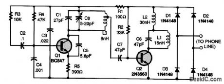
The circuit connects in series with either the tip or the ring (green or red) telephone line. Power for the circuit is full-wave bridge-rectified from the phone line by diodes Dl through D4. Transistor Q1, capacitors C1 and C8, and inductor L3 form an FM oscillator that operates at a frequency of around 93 MHz. Variable capacitor C8 allows the oscillator frequency to be adjusted between 90 and 95 MHz. To move the tuning area up to the 98- to 105-MHz range, C1 must be replaced with a 10-pF capacitor. Audio from the phone line is coupled through R3 and C2 to the base of Q1, where it frequency-modulates the oscillator. Transistor Q3, inductor L1, and capacitor C6 form a power amplifier. The signal tapped off L3 in the oscillator circuit is fed to the base of transistor Q2, and the FM signal is transmitted from Q2's collector. Inductor L2 is a radio-frequency shunt that decouples power and audio from the amplifier circuit. (View)
View full Circuit Diagram | Comments | Reading(150)
EMOTE_TELEPHONE_RINGER
Published:2009/7/14 3:09:00 Author:May
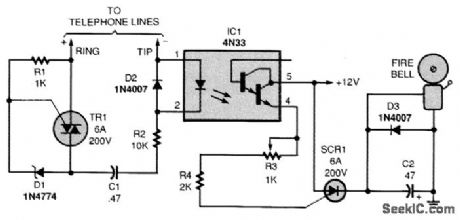
When there is no ring signal, the phone line's on-hook voltage (about 50 V) keeps the triac (Radio Shack 276-1001 or equivalent) from switching on, so the optocoupler doesn't conduct. When the phone rings, terminal 4 of the optocoupler feeds pulses through R3 and R4 to the gate of SCR1. The activated SCR connects the bell to the 12-V supply. Pulses are about 400 Hz, so the bell might sound a bit rough. The opening of the bell's breaker points cuts the thyristor's holding current to stop it from conducting when the gate signal stops. A 12-V, 2-A power supply operates the unit. Adjust R3 high enough so that the SCR is not triggered between rings, but low enough to trigger it when the phone is ringing. (View)
View full Circuit Diagram | Comments | Reading(2136)
REMOTE_TELEPHONE_BELL_RINGER
Published:2009/7/14 3:06:00 Author:May
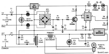
The telephone-line extension bell ringer shown will enable you to add a remote ringer in your garage or some other area where a ringing telephone cannot be heard Up to Four ringers can be used on a single telephone line, and a remote bell can be used 100 feet or more away from the unit.By substituting a light bulb for T2 and dispensing with the bell,the circuit can be made useful for the hearing-impaired.About 50 to 60 V dc is present between the tip and ring (red and green) wires of an unoccupied telephone line.Capacitor C1 blocks that dc voltage.The MOV just shunts any dialing pulses generated by a rotary phone that might be on the same line To make the phone ring,the tip and ring wires deliver an ac signal of between 90 and 130 V to the phone That ac signal is coupled through C1 to the neon lamps,NE1 and NE2 Those neon bulbs provide line isolation between the unit and the telephone line. They also neon fire (ionize) when more than 100 V is present on the phone line (in other words, during the ring signal). When they fire, they form a three-step voltage divider with the bridge rectifier. The voltage across the bridge is rectified, then filtered by R1, R2, C2, and C3, and causes Q1 to conduct. Then pins 2 and 6 of U1 go low, causing pin 3 of U1 to go high. The optoisolator and triac then turn on, applying power to the remote bell through a doorbell transformer (T2). (View)
View full Circuit Diagram | Comments | Reading(2096)
FM_TELEPHONE_BUG
Published:2009/7/14 2:32:00 Author:May
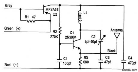
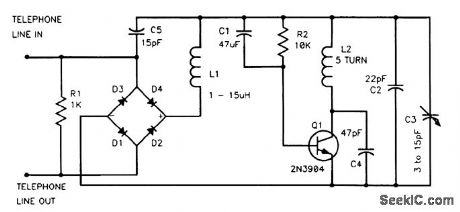
Q1 is an oscillator tuned to a quiet spot in the FM broadcast band. Dc from the line powers the bug. Connect the gray wire to the phone in place of the green wire, and the green wire on the bug to the green line wire. The red wire goes to the red phone line wire. Audio on the line causes incidental FM, which can be heard on an FM receiver tuned to the frequency of the oscillator. Because this device sees the full line voltage, Q2 is a high-voltage PNP MPSA56 transistor.Warning: Use of this device for certain purposes could violate federal and/or state laws and subject the violator to prosecution. (View)
View full Circuit Diagram | Comments | Reading(2147)
LOW_POWER_FM_TELEPHONE_BUG
Published:2009/7/14 2:29:00 Author:May
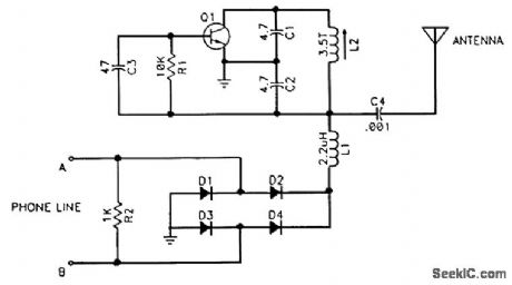
Q1 (2N3904) is an oscillator tuned to a quiet spot in the FM broadcast band. D1 through D4 (1N914) ensure proper polarity. Dc from the line powers the bug. Audio on the line causes incidental FM, which can be heard on an FM receiver tuned to the frequency of the oscillator. Warning: Use of this device for certain purposes could violate federal and/or state laws and subject the violator to prosecution. (View)
View full Circuit Diagram | Comments | Reading(2674)
TELEPHONE_BUG
Published:2009/7/14 2:35:00 Author:May
Q1 is an oscillator tuned to a quiet spot in the FM broadcast band. Dc from the line powers the bug. Diodes D1 through D4 ensure proper polarity. R1 maintains a suitable voltage drop for the bug. Audio on the line causes incidental FM, which can be heard on an FM receiver tuned to the frequency of the oscillator.Warning: Use of this device for certain purposes could violate federal and/or state laws and subject the violator to prosecution. (View)
View full Circuit Diagram | Comments | Reading(796)
Telephone electronic lock circuit diagram
Published:2011/8/4 5:07:00 Author:Rebekka | Keyword: Telephone electronic lock
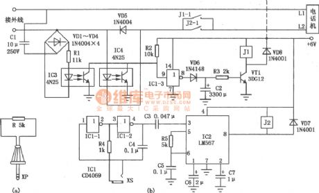
Telephone electronic lock uses the key (there is a resistance plug)inserts into the circuit and makes the periodic circuit start to oscillation. And the accuracy of the oscillation frequency can decide whether the telephone call can be opened and the receive of the external calls will not be affected. This can make sure that only the man who owns the key can uses the telephone. The circuit of the telephone electronic lock is shown as above. It is mainly composed of frequency key unlock circuit, ringing signal identifyinglock circuit, self-locking lock circuit and other components.
(View)
View full Circuit Diagram | Comments | Reading(1253)
High voltage speed optocoupler and application circuit diagram
Published:2011/8/4 5:03:00 Author:Rebekka | Keyword: High voltage speed optocoupler , application circuit

High speed optocouplers, its technical parameters are as follows: Rise time t1 ≤ 300ns; Circuit eye transfer ratio CTR = 50%; Isolation voltage VSO ≥ 15000V; Output transistor reverse breakdown voltage V (BR) CEO ≥ 50V.
The optical coupler can be widely used for the high-voltage isolators, high-voltage pulse transformers and high-voltage power circuit voltage stability control system. The control systems is used for high voltage regulator circuit. The fast high-voltage electrical coupling in this circuit play two roles. First one is to achieve the output voltage feedback loop in the input circuit and high voltage isolation between the low-voltage circuits; The other role is to achieve high output voltage feedback signal.
Note: The high pressure side +27 V DC power supply is independent, but its pressure level must be greater than 15KV. (View)
View full Circuit Diagram | Comments | Reading(2590)
70_V_INPUT_5_V_700_mA_TELECOM_CONVERTER
Published:2009/7/13 2:27:00 Author:May
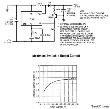
Telecom dc-to-dc conversion applications are usually complex because of the wide input voltage range of -30 to -70 V. Either big, expensive converter modules or space- and component-intensive discrete solutions are normally required to handle these higher voltages. The LT1082 contains a 1-A switch that can handle 100 V, enabling a -48-V-to-5-V converter to be designed with minimal size and cost. Features include foldback of the 60-kHz switching frequency under short-circuit condi-tions, protecting the LT1082 and power components from excessive power dissipation. The LT1082 dc-to-dc converter circuit provides up to 750 mA of output current, and the solution costs less than a modular supply of similar capabilities. (View)
View full Circuit Diagram | Comments | Reading(875)
DIODE_MATCHING_CIRCUIT_II
Published:2009/7/16 20:43:00 Author:Jessie
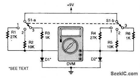


To match diode pairs with this circuit, simply insert diodes of equal rating in the D1 and D2 positions. When the DVM reading drops to zero or nearly zero, you have found a set. D1 and D2 are diodes under test. S1-a and S1-b select currents of 8 mA, 800μA, or 250μA. (View)
View full Circuit Diagram | Comments | Reading(937)
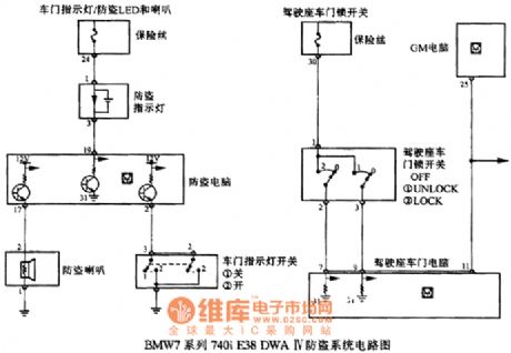
BMW7 series 740i E38DWA IV anti-theft system circuit
Published:2011/7/19 10:28:00 Author:Nancy | Keyword: anti-theft system , BMW7 series
View full Circuit Diagram | Comments | Reading(816)
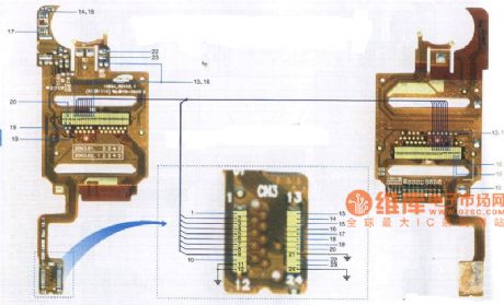
Kejian K518 mobile phone component cable distribution diagram
Published:2011/8/3 21:38:00 Author:Ecco | Keyword: Kejian , mobile phone , component cable distribution
View full Circuit Diagram | Comments | Reading(1274)
Inspur CU100 mobilephone cable connection diagram
Published:2011/8/3 21:47:00 Author:Ecco | Keyword: Inspur , mobilephone cable connection

View full Circuit Diagram | Comments | Reading(786)
| Pages:25/126 At 202122232425262728293031323334353637383940Under 20 |
Circuit Categories
power supply circuit
Amplifier Circuit
Basic Circuit
LED and Light Circuit
Sensor Circuit
Signal Processing
Electrical Equipment Circuit
Control Circuit
Remote Control Circuit
A/D-D/A Converter Circuit
Audio Circuit
Measuring and Test Circuit
Communication Circuit
Computer-Related Circuit
555 Circuit
Automotive Circuit
Repairing Circuit