
Electrical Equipment Circuit
Index 32
FRENCH_COLOR_TV_CHROMINANCE
Published:2009/7/20 21:58:00 Author:Jessie
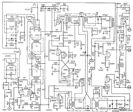
SECAM system uses time multiplexing of two chrominance signals, transmitted sequentially, with one-line memory in receiver circuit.-R. Chaste, P. Cassagne, and M. Colas, Sequential Receivers for French Color Tv System, Electronics, 33:19, p 57-60. (View)
View full Circuit Diagram | Comments | Reading(1371)
107_MHz_IF_amplifier_using_a_3N204_dual_gate_MOSFET
Published:2009/7/20 22:21:00 Author:Jessie

10.7 MHz IF amplifier using a 3N204 dual-gate MOSFET (courtesy Texas Instruments Incorporated). (View)
View full Circuit Diagram | Comments | Reading(1994)
COLOR_VIDEO_I_F
Published:2009/7/20 22:21:00 Author:Jessie
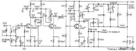
Three-stage amplifier has forward agc on first stage Q1. Sound trap at 41.25 Mc before detection prevents 900-Mc beat between color subcarrier and sound carrier. -D. Bray, Solid State Makes Debut in Big-Screen Color Tv, Electronics, 39:8, p 99- 105. (View)
View full Circuit Diagram | Comments | Reading(827)
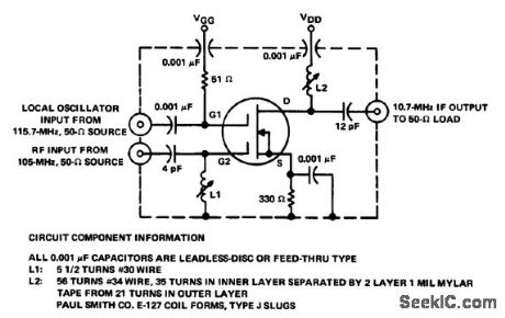
105_MHz_to_107_MHz_converter_using_a_3N225_dual_gate_MOSFET
Published:2009/7/20 22:19:00 Author:Jessie
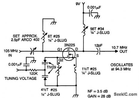
105 MHz to 10.7 MHz converter using a 3N225 dual-gate MOSFET (courtesyTexas Instruments Incorporated). (View)
View full Circuit Diagram | Comments | Reading(841)
COLOR_BURST_AMPLIFIER
Published:2009/7/20 22:19:00 Author:Jessie
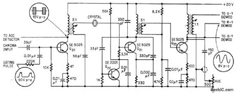
Burst amplifier Q20 and 3.58-Mc crystal oscillator Q21 are driven by output of 0rst stage of chroma amplifier of transistorized color tv. Amplifier burst locks oscillator frequency to subcarrier frequency required by color demodulators, and provides reference burst for automatic color control circuit.-D. Bray, Solid State Makes Debut in Big4creen Color Tv, Electronics, 39:8, p 99-105. (View)
View full Circuit Diagram | Comments | Reading(875)
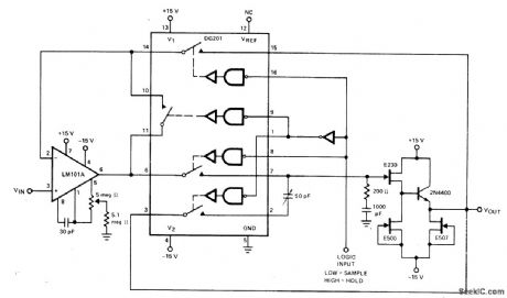
COLOR_HOLD
Published:2009/7/20 22:18:00 Author:Jessie
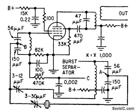
Uses passive fiber to separate color subcarrier frequency front sync burst, along with injection-locked oscillator that combines amplitude limiting and power amplification for direct drive of color demodulators.-I. N. Moth, Locked Oscillator for Color Tv, Electronics, 32:39, p 91-92. (View)
View full Circuit Diagram | Comments | Reading(835)
BALANCED_DIODE_COLOR_BURST_GATE
Published:2009/7/20 22:17:00 Author:Jessie
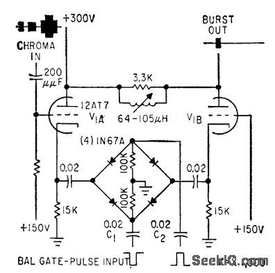
Used in automatic video-processing amplifier that instantly compensates for wide variations in color or monochrome input signal levels, to maintain output signal components al correct levels.-J. O. Schroeder, Holding Video Levels While Switching Studios, Electronics, 32:22, p 96-98. (View)
View full Circuit Diagram | Comments | Reading(826)
COLOR_AGC
Published:2009/7/20 22:17:00 Author:Jessie
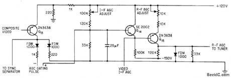
Supplies bias voltage to r-f and video i-f stages of color set using transistors in all but deflection and recliner stages, to maintain video output amplitude at about 3 v.-D. Bray, Solid State Makes Debut in Big-Screen Color Tv, Electronics, 39:8, p 99-105 (View)
View full Circuit Diagram | Comments | Reading(684)
107_MHz_to_455_kHz_mixer_for_CB_operation_using_a_TIS148_dual_gate_MOSFET
Published:2009/7/20 22:16:00 Author:Jessie

10.7 MHz to 455 kHz mixer for CB operation using a TIS148 dual-gate MOSFET (courtesy Texas Instruments Incorporated). (View)
View full Circuit Diagram | Comments | Reading(1939)
REFERENCE_OSCILLATOR_FOR_COLOR_TV_KLYSTRON
Published:2009/7/20 22:12:00 Author:Jessie
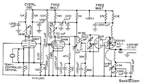
Used in afc system that locks 2,000-Mc klystron to crystal oscillator reference frequency. Receiving-tube multipliers provide 50 mw at 500 Mc, and silicon crystal diode quadruples this to give 0.25 mw ct 2,000 Mc. Used in mobile microwave relay system for color tv pickups.-T. G. Custin and J. Smith, Relay System Diplexes Audio and Color Video, Electronics, 31:25, p 64-67. (View)
View full Circuit Diagram | Comments | Reading(1451)
GLITCH_CANCELLATION
Published:2009/7/20 22:11:00 Author:Jessie
Fourth section of DG201 quad CM0S analog switch provides cancellation of coupled charges (glitches), to keep sample-and-hold offset below 5 mV over analog voltage range of -10 V to +10 V. Acquisition time is 25μs for opamp shown but can be im-proved by using faster-slewing opamp. Aperture time is typically 1 ps- Analog Switches and Their Applications, Silliconix, Santa Clara,CA,1976,p 7-68. (View)
View full Circuit Diagram | Comments | Reading(1491)
LUMINANCE_AMPLIFIER
Published:2009/7/20 22:10:00 Author:Jessie
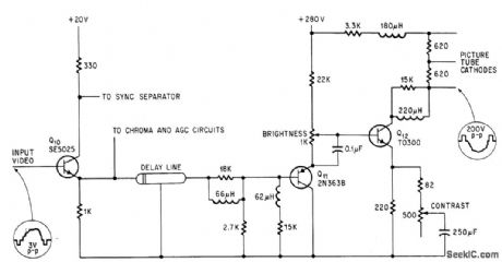
Provides bandwidth of 2 Mc, with 200.v output, for color set having transistors in all except defection and rectifier circuits. Brightness is controlled by shifting base bias voltage of Q12, and contrast by varying ac emitter impedance of Q12.-D. Bray, Solid State Makes Debut in Big-Screen Color Tv, Electronics, 39:8, p 99-105. (View)
View full Circuit Diagram | Comments | Reading(828)
AUTOMATIC_CHROMA_CONTROL
Published:2009/7/20 22:09:00 Author:Jessie
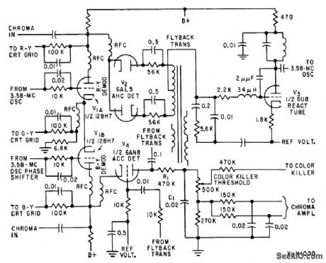
Improves stability of hue, saturation, noise, and pull in characteristics of received color tv signals. Low-frequency diode gate corrects subcarrier oscillator phase from synchronous demodulator signals and establishes signal level for a chromo control circuit.-Z. Wiencek, Automatic Controls for Color Television, Electronics, 32:20, p 58-59. (View)
View full Circuit Diagram | Comments | Reading(790)
AUTOMATIC_FINE_TUNING
Published:2009/7/20 22:08:00 Author:Jessie
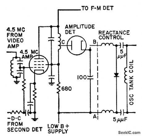
Amplitude of 4.5-Mc intercarrier sound signal controls sound-to-picture ratio to provide automatic lne tuning. Automatic control of beats between picture harmonics and sound carrier closely approximates manual tuning. Circuit is particularly valuable for remote control of color tv sets. -C. W. Bough, Jr., and L. J. Sienkiewicz, Sound Signal Tunes Tv Automatically, Electronics, 31:17, p 54-58. (View)
View full Circuit Diagram | Comments | Reading(759)
AFC_FOR_COLOR_TV_KLYSTRON
Published:2009/7/20 22:07:00 Author:Jessie
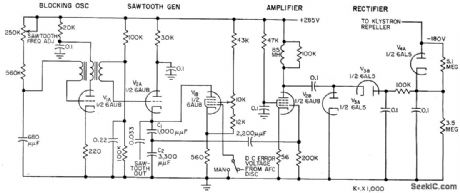
Used with visual f-m transmitter for microwave ralay. Klystron locks to crystal i-f difference frequency to provide required high degree of stability. Calibrated wavetrap modifies sawtooth waveshape of afc to provide internal frequency monitoring. -T .-G. Custin and J. Smith, Relay System Diplexes Audio and Color Video, Electronics, 31:25, p 64-67 (View)
View full Circuit Diagram | Comments | Reading(844)
FAST_SAMPLE_AND_HOLD
Published:2009/7/20 21:42:00 Author:Jessie
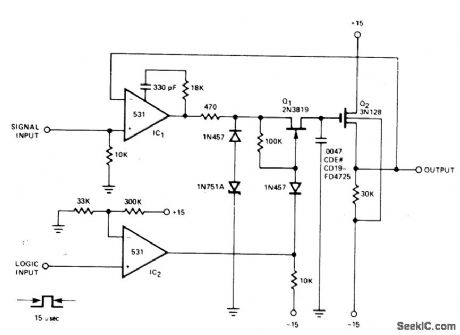
Strobe pulse developed from logic input of 531 opamp IC, turns on JFET Q1 to complete feedback loop to IC1, Q1, and Q2. C1 charges to voltage equal to that of input signal plus gate-to-source offset voltage of Q2. At end of strobe time, feedback loop is broken and C, holds voltage until time of next strobe pulse. Decay in output voltage between samplings is 1mV/s.- Signetics Analog Data Manual, Signetics, Sunnyvale, CA, 1977, p 643-644. (View)
View full Circuit Diagram | Comments | Reading(1070)
105_MHz_gate_2_contralled_RF_amplifier_using_a_TIS152_dual_gate_MOSFET
Published:2009/7/20 22:34:00 Author:Jessie
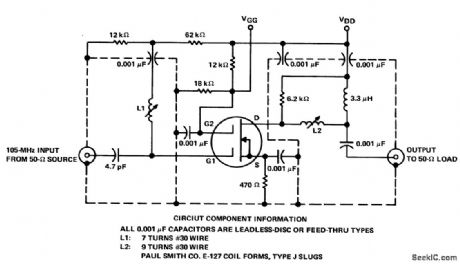
105 MHz gate-2-contralled RF amplifier using a TIS152 dual-gate MOSFET This circuit has been optimized for third-order intermodulation distortion(courtesy Texas Instruments Incorporated). (View)
View full Circuit Diagram | Comments | Reading(1501)
118_to_136_MHz_broadband_RF_amplifier_using_a_2N6083_bipolar_transistor
Published:2009/7/20 22:31:00 Author:Jessie
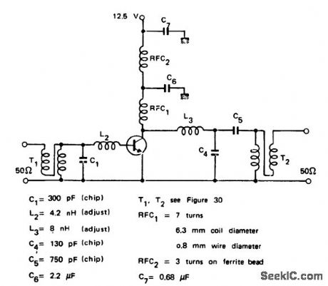
118 to 136 MHz broadband RF amplifier using a 2N6083 bipolar transistor. This circuit is ideal for mobile operation since the recommended supply voltage is 12.5 volts. It provides 30 watts output for a 4-watt input at 125 MHz (courtesy Motorola Semiconductor Products Inc.). (View)
View full Circuit Diagram | Comments | Reading(2511)
105_MHz_to_107_MHz_mixer_using_a_TIS152_dual_gate_MOSFET
Published:2009/7/20 22:28:00 Author:Jessie
105 MHz to 10.7 MHz mixer using a TIS152 dual-gate MOSFET (courtesy Texas Instruments Incorporated). (View)
View full Circuit Diagram | Comments | Reading(2509)
4_digit_CMOS_gas_discharge_display_
Published:2009/7/20 22:22:00 Author:Jessie
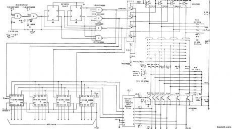
4-digit CMOS gas discharge display (courtesy Motorola Semiconductor Products Inc.). (View)
View full Circuit Diagram | Comments | Reading(1015)
| Pages:32/126 At 202122232425262728293031323334353637383940Under 20 |
Circuit Categories
power supply circuit
Amplifier Circuit
Basic Circuit
LED and Light Circuit
Sensor Circuit
Signal Processing
Electrical Equipment Circuit
Control Circuit
Remote Control Circuit
A/D-D/A Converter Circuit
Audio Circuit
Measuring and Test Circuit
Communication Circuit
Computer-Related Circuit
555 Circuit
Automotive Circuit
Repairing Circuit