
Circuit Diagram
Index 2042
Circuit Of CXA1034P/1034M Single Cassette Stereo Player
Published:2011/4/20 8:07:00 Author:TaoXi | Keyword: Single Cassette, Stereo Player
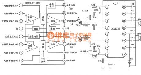
Left figure is the internal circuit diagram of the CXA1034P/1034M, and the right figure is the typical application circuit of it. (View)
View full Circuit Diagram | Comments | Reading(935)
Circuit of Encryption Wireless TV
Published:2011/4/20 7:52:00 Author:TaoXi | Keyword: Encryption, Wireless, TV
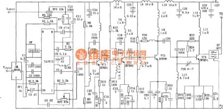
The circuit of encryption wireless TV with 1W transmit power is as shown. The input signal are audio and video signals, and the launch channel is decided by the SW SAW resonator in modulation circuit. Video signal that sent by the cameras, video recorders, VCD and other equipment will transport into the 3-pin of the encryption module of the transmitter, then output the encrypted video signal, and modulated in to the RF signals by modulation circuit, VT1, VT2 voltage amplification, VT3 promote amplification, VT4 power amplifier, at last launch out by the antenna. Because of the VTl ~ VT4 is amplified by broadband (46~870MHz), so between the power amplifier and antenna band-pass filter need to use the bandpass filter to prevent the band emissions.
The decryption receiver is composed of TDQ-3 tuner, finished TA7680 board and the decryption module, as shown in the figure. Receiver receives the transmitted signal, converses the frequency in high-frequency tuner, and outputs the 38MHz IF signal, outputs audio signal and the encrypted video signal, and after decrypted by the decryption module 8910, we get the video signal to watch. (View)
View full Circuit Diagram | Comments | Reading(1842)
Circuit Of KA22131 Single Cassette Stereo Player
Published:2011/4/20 8:07:00 Author:TaoXi | Keyword: Single Cassette, Stereo Player, KA22131
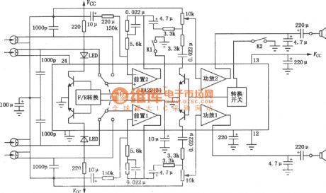
The Circuit Of KA22131 Single Cassette Stereo Player is as shown. (View)
View full Circuit Diagram | Comments | Reading(707)
Ultrasonic Transmitter and Receiver Circuit
Published:2011/4/20 8:02:00 Author:TaoXi | Keyword: Ultrasonic, Transmitter, Receiver
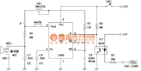
The Ultrasonic Transmitter and Receiver Circuit is as shown. (View)
View full Circuit Diagram | Comments | Reading(1615)
The Circuit Of MIC5157 Positive Edge Triggered Switch
Published:2011/4/20 8:36:00 Author:TaoXi | Keyword: Positive Edge, Triggered
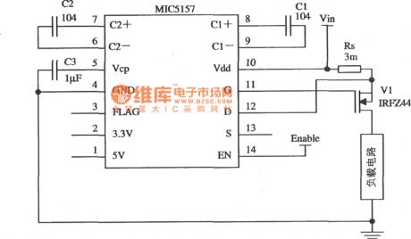
The Circuit Of MIC5157 Positive Edge Triggered Switch
(View)
View full Circuit Diagram | Comments | Reading(604)
SHANGHAI GM BUICK(Royaum)saloon car 3.6L engine circuit diagram(seven)
Published:2011/4/20 21:30:00 Author:muriel | Keyword: SHANGHAI GM BUICK(Royaum), saloon car , 3.6L engine
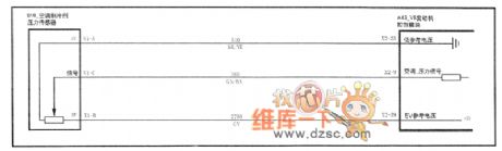
Figure SHANGHAI GM BUICK(Royaum)saloon car 3.6L engine circuit diagram(seven)--air condition refrigeration pressure sensor (View)
View full Circuit Diagram | Comments | Reading(445)
SHANGHAI GM BUICK(Royaum)saloon car 3.6L engine circuit diagram(eight)
Published:2011/4/20 21:30:00 Author:muriel | Keyword: SHANGHAI GM BUICK(Royaum), saloon car, 3.6L engine
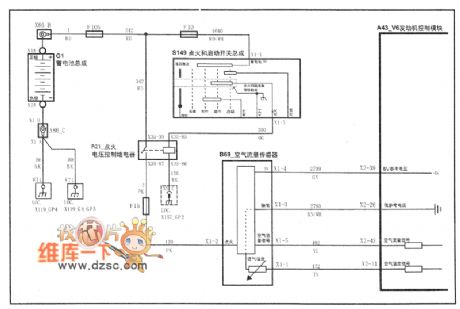
Figure SHANGHAI GM BUICK(Royaum)saloon car 3.6L engine circuit diagram(eight)--air flow meter and air inlet temperature sensor (View)
View full Circuit Diagram | Comments | Reading(555)
Reference voltage source using complementary transistors
Published:2011/4/14 6:44:00 Author:may | Keyword: Reference voltage source, complementary transistors

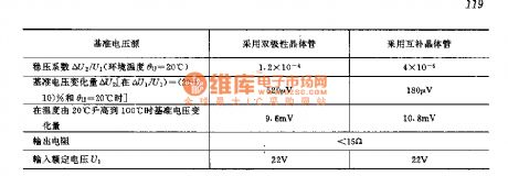
The characteristic of this circuit is shown in the following table ( RL=68kΩ)
reference voltage source
adopts BJT
adopts complementray transistor
voltage-regulation coefficient △U2/U1 ( enviromental termeprature θu=20 ℃)
1.2×10⁻⁴
4×10⁻⁵
variation of voltage reference △U2[when △U1/U1=(20±10)% and θu=20℃]
520μV
180μV
variation of voltage reference when the temperature rise from 20℃ to 100℃
9.6mV
10.8mV
output resistor
<15Ω
input rated voltage U1
22V
22V (View)
View full Circuit Diagram | Comments | Reading(588)
SHANGHAI GM BUICK(Royaum)saloon car 3.6L engine circuit diagram(eleven)
Published:2011/4/20 21:36:00 Author:muriel | Keyword: SHANGHAI GM BUICK(Royaum), saloon car, 3.6L engine
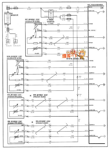
Figure SHANGHAI GM BUICK(Royaum)saloon car 3.6L engine circuit diagram(eleven)---oxygen sensor (View)
View full Circuit Diagram | Comments | Reading(626)
Reference voltage source using operational amplifier
Published:2011/4/14 4:38:00 Author:may | Keyword: Reference voltage source, operational amplifier
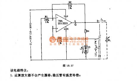
The features of this circuit:
1 operational amplifier will not cause drift, voltage regulator tube have thecharacteristic of temperature compensation
2 the output voltage of pin 3 is very low, so, output current must higher than 10mA, it has no influence to voltage regulator performance and drift characteristic
3 choosing appropriately among R1、R2 and R4 can make the output voltage has a wider range (U3>U2) . (View)
View full Circuit Diagram | Comments | Reading(653)
SHANGHAI GM BUICK(Royaurm)saloon car 3.6L engine circuit diagram(fourteen)
Published:2011/4/20 21:29:00 Author:muriel | Keyword: SHANGHAI GM BUICK(Royaurm), saloon car , 3.6L engine
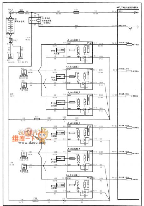
Figure SHANGHAI GM BUICK(Royaurm)saloon car 3.6L engine circuit diagram(fourteen)--ignition coil (View)
View full Circuit Diagram | Comments | Reading(786)
SHANGHAI GM BUICK(Royaum)saloon car 3.6L engine circuit diagram(thirteen)
Published:2011/4/20 21:33:00 Author:muriel | Keyword: SHANGHAI GM BUICK(Royaum), saloon car , 3.6L engine
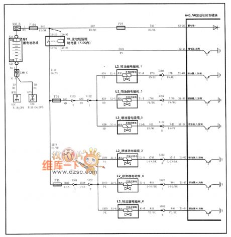
Figure SHANGHAI GM BUICK(Royaum)saloon car 3.6L engine circuit diagram(thirteen)---fuel injector (View)
View full Circuit Diagram | Comments | Reading(442)
Circuit Of Car Audio Speaker
Published:2011/4/20 9:05:00 Author:TaoXi | Keyword: Car Audio
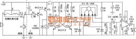
The figure shows the circuit of car audio speaker. The left of dotted line is the circuit of original electric speaker, Sl means the electric speaker button switch on the steering wheel. S2 is the additional SPDT, for the switch between the original car electric horn and voice horn. When the switch S2 set to 2 , press the switch Sl, capacitor Cl is charged, transistor VTl, VT2 conducted, relay Jl picked, its normally open contact point J1-1 closed for 15 seconds to supply power to the circuit. ICl is designed as the dedicated voice circuits HL-169A, because of its working time is 2.8 seconds, so use the transistor VT3, VT4 to form the self-excited multivibrator, export a high level as a trigger signal per three seconds, this makes ICl export a voice signal per three seconds, transports into IC2 to enlarge the audio power, at last speaker BL issues the voice.
(View)
View full Circuit Diagram | Comments | Reading(769)
The application circuit of pulse width modulated type switching stabilized voltage supply
Published:2011/4/19 4:00:00 Author:May | Keyword: pulse width modulated, switching, stabilized voltage supply
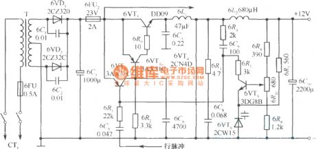
In the diagram it is an actual example of pulse width modulated switching regulated power supply. It is Kaige 4D17U type which is produced by Shanghai the fourth radio factory. It is stabilized voltage supply of 35cm black and white TV set.
Its main technical target is shown in the following:
Output voltage: 12V;
Output current: 1A’
Power consumption <20W;
Efficiency >64%
Internal resistance <0.075Ω;
Ripples <15mV;
Commercial power voltage: 160~240V.
In the diagram, full wave rectification circuit consists of 6VD1, 6VD2; 6C3 is filter capacitor; 6C1, 6C2 is used to slack down surge current; free running multi-vibrator consists of 6VT7, 6VT2, 6VT3 and 6VT4, 6C9. At the same time, 6VT7 is switching tube.
When 12V output voltage reduced because of some reasons, the voltage which is got from sample circuit 6R6, 6R9, and 6R8 by error amplifier tube 6VT5 is also reducing. 6VT5’s collector voltage is rising. 6VT3’s base level is rising too. The output pulse of 6VT7 is broadening. Then the reduced voltage is rising again. On the contrary, when output voltage reduced, we can opposite adjust according to this process above mentioned. It can let the output voltage remain stable. (View)
View full Circuit Diagram | Comments | Reading(1701)
SHANGHAI GM BUICK(Royaum)saloon car 3.6L engine circuit diagram(fifteen)
Published:2011/4/20 21:33:00 Author:muriel | Keyword: SHANGHAI GM BUICK(Royaum), saloon car, 3.6L engine
Figure SHANGHAI GM BUICK(Royaum)saloon car 3.6L engine circuit diagram(fifteen)--vapor emission sewage disposal solenoid valve (View)
View full Circuit Diagram | Comments | Reading(458)
Simplified Multi-Resonant Generator Circuit
Published:2011/4/20 21:33:00 Author:Sue | Keyword: Simplified, Multi-Resonant, Generator
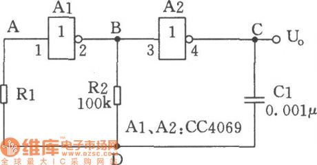
As seen in the figure is the circuit of simplified multi-resonant generator composed of CC4069 inverters. This circuit applies to the low frequency clock oscillatory circuit with less focus on frequency stability and accuracy. (View)
View full Circuit Diagram | Comments | Reading(547)
Single phase full-wave rectification double filtering circuit diagram
Published:2011/4/20 21:19:00 Author:muriel | Keyword: Single phase , full-wave rectification , double filtering
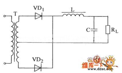
Single phase full-wave rectification double filtering circuit diagram is as shown
(View)
View full Circuit Diagram | Comments | Reading(779)
low power consumption single phase half-wave rectification capacitor filtering circuit diagram
Published:2011/4/20 21:16:00 Author:muriel | Keyword: low power consumption, single phase, half-wave rectification capacitor filtering
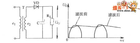
low power consumption single phase half-wave rectification capacitor filtering circuit diagram is as shown
(View)
View full Circuit Diagram | Comments | Reading(1114)
SHANGHAI GM BUICK(Excelle)saloon car rearview mirror circuit diagram
Published:2011/4/20 21:09:00 Author:muriel | Keyword: SHANGHAI GM BUICK(Excelle), saloon car , rearview mirror
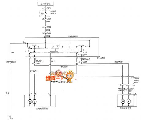
Figure SHANGHAI GM BUICK(Excelle)saloon car rearview mirror circuit diagram (View)
View full Circuit Diagram | Comments | Reading(466)
SHANGHAI GM BUICK(Excelle)saloon car fog dispersal system circuit diagram
Published:2011/4/20 21:11:00 Author:muriel | Keyword: SHANGHAI GM BUICK(Excelle), saloon car, fog dispersal system
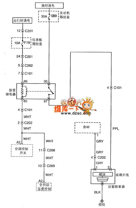
Figure SHANGHAI GM BUICK(Excelle)saloon car fog dispersal system circuit diagram (View)
View full Circuit Diagram | Comments | Reading(427)
| Pages:2042/2234 At 2020412042204320442045204620472048204920502051205220532054205520562057205820592060Under 20 |
Circuit Categories
power supply circuit
Amplifier Circuit
Basic Circuit
LED and Light Circuit
Sensor Circuit
Signal Processing
Electrical Equipment Circuit
Control Circuit
Remote Control Circuit
A/D-D/A Converter Circuit
Audio Circuit
Measuring and Test Circuit
Communication Circuit
Computer-Related Circuit
555 Circuit
Automotive Circuit
Repairing Circuit