
Circuit Diagram
Index 2051
AC 220V-DC 5V/10A switching power supply
Published:2011/4/20 2:11:00 Author:May | Keyword: AC 220V-DC 5V/10A, switching power supply
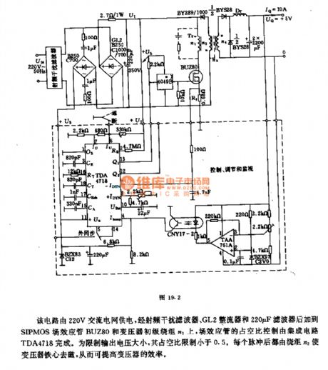
This circuit is energy supply by 220V AC network. It adds to SIPMOS FET BUZ80 and transformer primary winding n1 after passing radio interference filter, GL2 rectifier and 220μF filter. The duty factor control of FET is finished by integrated circuit TDA4718. Its duty factor limiting must less than 0.5 in order to limit the size of output voltage. Winding n2 can make transformer magnet core to degaussing after every pulse. Thereby it can improve the efficiency of transformer.
Transformer data: n1=112 turns, 15×0.1mm copper lacquered wire;
n2=112 turns, 12×0.04mm copper lacquered wire;
n3=1 turn, shield thin foil.
Choke data: 10 turns, 4×30×1mm copper lacquered wire. (View)
View full Circuit Diagram | Comments | Reading(3002)
AC 110V-DC 5V/10A switching power supply
Published:2011/4/20 2:15:00 Author:May | Keyword: AC 110V-DC 5V/10A, switching power supply
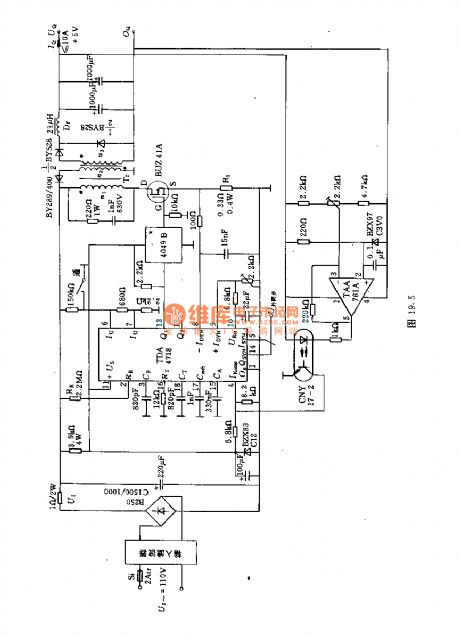
This circuit is energy supply by 110V AC network. It adds to SIPMOS FET BUZ80 and transformer primary winding n1 after rectifying and filtering. The duty factor control of FET is finished by integrated circuit TDA4718. Its duty factor must less than 0.5. Winding n2 can make transformer magnet core to degaussing after every pulse in order to improve the efficiency.
(View)
View full Circuit Diagram | Comments | Reading(3039)
Single-ended fly-back converter switching power supply principle diagram
Published:2011/4/19 1:40:00 Author:May | Keyword: Single-ended, fly-back, converter switching, power supply
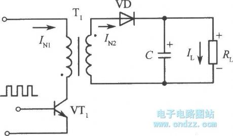
Single-ended fly-back converter switching regulated power supply is not only consisting of a transistor. Two transistors also can make up single-ended converter type switching regulated power supply. The basic difference between single-ended fly-back switching regulated power supply and push pull, full bridge, half bridge two ends converter switching regulated power supply is the magnetic core of high frequency transformer only works on one side of magnetic hysteresis loop (first quadrant). Typical single-ended fly-back converter switching regulated power supply principle diagram is shown in the diagram. So called single end is the magnetic core of converting circuit is only working on one side of its magnetic hystersis loop. So called fly back is storage energy at primary winding when transistor is breaking over and the storage energy releasing to load by secondary coil when transistor is cutting off. When switching tube VT1 is breaking over by encouraging of controlled pulse, input voltage Ui will add to primary winding N1 of high frequency transformer. Vice-side winding N2 has not current because rectifier diode VD of transformer T1's vice-side winding is reverse connecting. (View)
View full Circuit Diagram | Comments | Reading(1172)
Automatic charger circuit of homemade nickel-cadmium battery
Published:2011/4/17 22:09:00 Author:May | Keyword: Automatic charger, homemade, nickel-cadmium battery

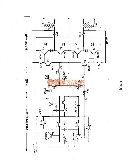
This charger of nickel-cadmium battery adopts given voltage to control charging. It can automaticly stop to charge when the battery voltage reach to prescribed value.working principleThe circuit is shown in diagram 4-16. Commercial power passes transformer, rectifier circuit composed of transformer T and rectifier diode VD1~VD4. Then the commercial power is filtering and outputing DC voltage by capacitor C1. Resistor R1 and LED H1 make up working power light. Three teminal regulator integrated package IC and reistor R2, R3 make up constant current circuit. The peripheral cell is Triode VT, integrated circuit LM324 and transfer switch S2 and so on. They make up constant voltage control switch circuit. Voltage regulator tube VD6 and resistor R5, R6, R7 make up charge circuit to battery. LM324's pin 6 connects standard control voltage. LM324's pin 5 connects anode of battery. When pin 5's voltage is lower than pin 6's (that is battery voltage is lower), pin 7 will output low voltage (0V). That is, pin 9's voltage si lower than pin 10's. Pin 8's output is high level, VT is turn on (that is power turn on).
(View)
View full Circuit Diagram | Comments | Reading(1095)
VH5162 festival color lamp with "good luck" voice control circuit
Published:2011/4/20 3:34:00 Author:Nicole | Keyword: festival color lamp, voice
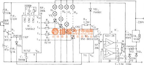
VH5162 is a CMOS festival color lamp control circuit, it has four ways color lamp drive output, eight work modes. The figure of festival color lamp with good luck voice control circuit is as shown. The change of work mode adopts clock sequence control way, the unijunction tube relaxation oscillator generator provides trigger clock. VT1(BT33) and R1,RP1,C1 and R2 form the low frequency relaxation oscillator, its oscillation period is:
The η is unijunction tube attenuation ratio, generally η=0.35~0.55. (View)
View full Circuit Diagram | Comments | Reading(493)
Shanghai General Motors Power Supply Circuit
Published:2011/4/20 2:21:00 Author:Robert | Keyword: Shanghai General Motors, Power Supply
View full Circuit Diagram | Comments | Reading(605)
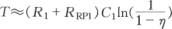
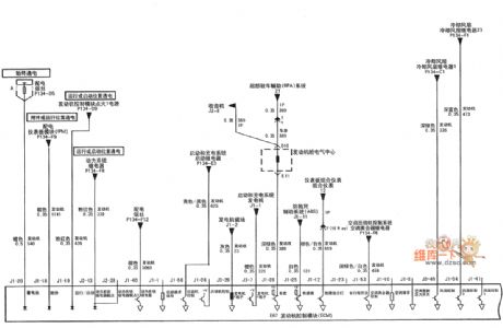
Shanghai General Motors System Circuit
Published:2011/4/20 2:20:00 Author:Robert | Keyword: Shanghai General Motors, System Circuit
View full Circuit Diagram | Comments | Reading(512)
tl494 application circuit 1
Published:2011/4/20 3:22:00 Author:Jessie | Keyword: application
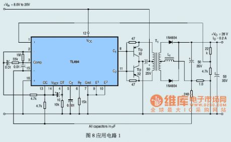
View full Circuit Diagram | Comments | Reading(13203)
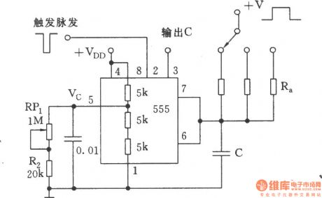
The precise timing circuit for correcting capacitor tolerance
Published:2011/4/20 3:32:00 Author:Ecco | Keyword: precise , timing circuit , correcting , capacitor tolerance
View full Circuit Diagram | Comments | Reading(571)
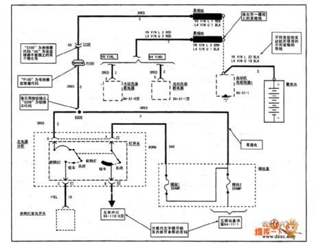
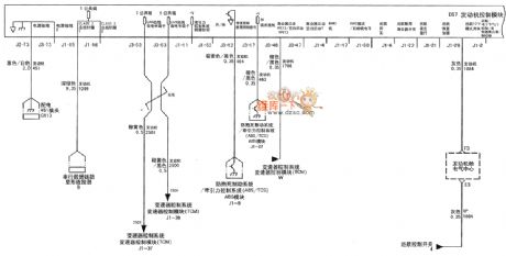
Shanghai General Buick LaCROSSE Car 3.0L Engine Circuit (1)
Published:2011/4/20 2:20:00 Author:Robert | Keyword: Shanghai General, Buick, LaCROSSE, 3.0L Engine
View full Circuit Diagram | Comments | Reading(515)
The delay circuit with "watchdog" composed of 555
Published:2011/4/20 3:29:00 Author:Ecco | Keyword: delay circuit , "watchdog" , 555
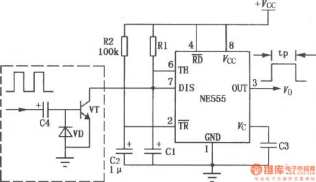
The circuit used to be a power-delay control circuit, the delay time is decided by the timing components Rl, C1. However, with a watchdog circuit, you can use it as monitoring circuitforsome applications.
(View)
View full Circuit Diagram | Comments | Reading(3558)
Current limit protection charger circuit with CW117
Published:2011/4/20 3:21:00 Author:Jessie | Keyword: Current limit protection, charger
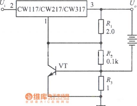
View full Circuit Diagram | Comments | Reading(693)
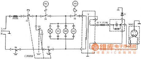
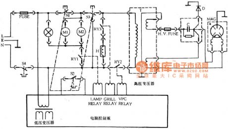
Glanze WP700 WP750 WP800 microwave circuit
Published:2011/4/20 3:18:00 Author:Jessie | Keyword: microwave
View full Circuit Diagram | Comments | Reading(709)
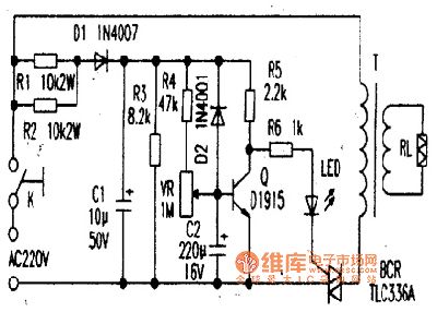
TLC336A bi-directional controllable thyristor application circuit
Published:2011/4/20 3:20:00 Author:Jessie | Keyword: bi-directional, thyristor, controllable, application
View full Circuit Diagram | Comments | Reading(1849)
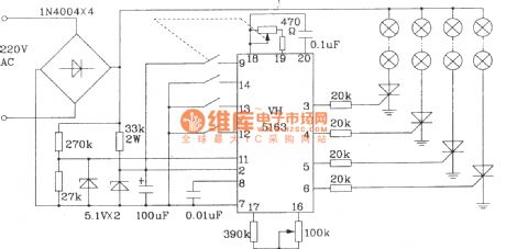
Typical application circuit of VH5163 color lamp control integrated circuit
Published:2011/4/20 3:22:00 Author:Nicole | Keyword: color lamp
View full Circuit Diagram | Comments | Reading(452)
Shanghai General Buick LaCROSSE Car 3.0L Engine Circuit (2)
Published:2011/4/20 2:19:00 Author:Robert | Keyword: Shanghai General, Buick, LaCROSSE, 3.0L Engine
View full Circuit Diagram | Comments | Reading(499)
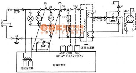
Glanze WD900B microwave circuit
Published:2011/4/20 3:18:00 Author:Jessie | Keyword: microwave
View full Circuit Diagram | Comments | Reading(604)
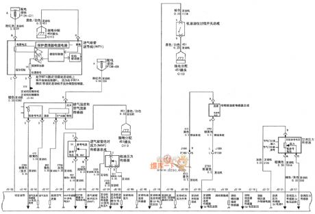
Shanghai General Buick LaCROSSE Car 3.0L Engine Circuit (3)
Published:2011/4/20 2:19:00 Author:Robert | Keyword: Shanghai General, Buick, LaCROSSE, 3.0L Engine
View full Circuit Diagram | Comments | Reading(616)
Shanghai General Buick LaCROSSE Car 3.0L Engine Circuit (4)
Published:2011/4/20 2:17:00 Author:Robert | Keyword: Shanghai General, Buick, LaCROSSE, 3.0L Engine

View full Circuit Diagram | Comments | Reading(530)
Glanze WD800 WD800BS microwave circuit
Published:2011/4/20 3:16:00 Author:Jessie | Keyword: microwave
View full Circuit Diagram | Comments | Reading(719)
| Pages:2051/2234 At 2020412042204320442045204620472048204920502051205220532054205520562057205820592060Under 20 |
Circuit Categories
power supply circuit
Amplifier Circuit
Basic Circuit
LED and Light Circuit
Sensor Circuit
Signal Processing
Electrical Equipment Circuit
Control Circuit
Remote Control Circuit
A/D-D/A Converter Circuit
Audio Circuit
Measuring and Test Circuit
Communication Circuit
Computer-Related Circuit
555 Circuit
Automotive Circuit
Repairing Circuit