
Circuit Diagram
Index 2052
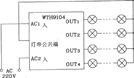
TWH9104 festival multi patterns flashing color lamp with "all the best" voice control circuit
Published:2011/4/20 3:17:00 Author:Nicole | Keyword: flashing color lamp, voice control
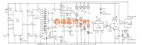
The circuit is as shown, it adopts TWH9104 color lamp control circuit as the core to form this circuit, the color lamp patterns are automatical selected by the pulse count or the distribution circuit according to time sequence and level grouping, that is programing and assembling to the different levels of pattern selection control terminal S0, S1, DIM, to achieve the automatic retread and flash change of the color lamp patterns. (View)
View full Circuit Diagram | Comments | Reading(537)
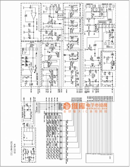
SAMSUNG CME20G microwave circuit
Published:2011/4/20 3:15:00 Author:Jessie | Keyword: microwave
View full Circuit Diagram | Comments | Reading(813)
Voltage frequency converter circuit composed of AD654
Published:2011/4/20 1:36:00 Author:Ecco | Keyword: Voltage frequency, converter
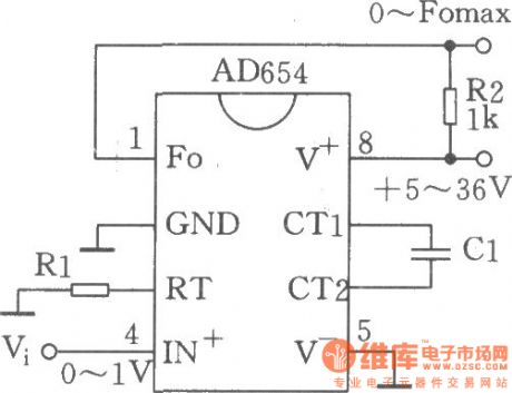
The circuit shown in the figure is low-cost voltage frequency converter (VFC) with AD654. Connecting to necessary components Rl and Cl according to figure will make a VFC application circuit. Supply voltage can still guarantee performance to l6.5V when it is as low as 4.5V. The maximum power consumption is 3mA (no load). The highest frequency is 520kHz. The input voltage range is limited to 0 ~ 4V. The input span Vi is decided by resistor Rl, that is Vi / Rl = lmA. For example, Vi = 0 ~ 1V, Rl = lkΩ, Vi = 0 ~ 5V, Rl = 5kΩ. Output frequency range is corresponding to the Cl, Fomax = l/l0Cl, the unit of C1 is μF. For example, Cl = 0.1μF, the output frequency is 0 ~ lkHz; Cl = 0.001> F, the output frequency range is 0 ~ l00kHz.
(View)
View full Circuit Diagram | Comments | Reading(3135)
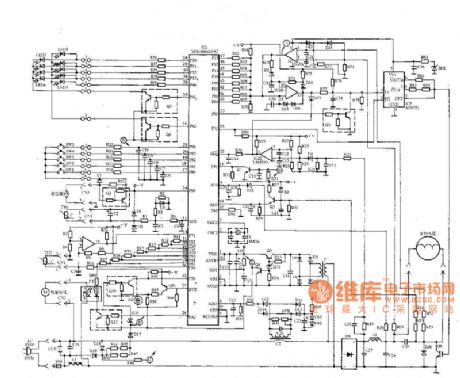
Complete induction cooker circuit
Published:2011/4/20 3:14:00 Author:Jessie | Keyword: induction cooker
View full Circuit Diagram | Comments | Reading(2407)
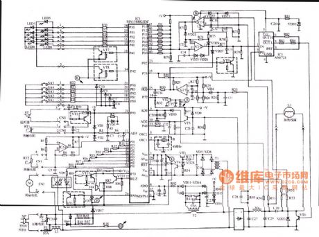
Application circuit of TWH9104 new type color lamp control integrated circuit
Published:2011/4/20 3:00:00 Author:Nicole | Keyword: color lamp,
In figure, the rectifier diode and SCR should use component with 200V withstand voltage. When the load power is more than 100W, according to the real power to change the diode and SCR. (View)
View full Circuit Diagram | Comments | Reading(528)
Panasonic induction cooker circuit
Published:2011/4/20 3:14:00 Author:Jessie | Keyword: induction cooker
View full Circuit Diagram | Comments | Reading(1565)
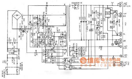
LQ-1600K printer power supply circuit
Published:2011/4/20 3:11:00 Author:Jessie | Keyword: printer power supply
View full Circuit Diagram | Comments | Reading(1145)
Delay light circuit with TRIAC(2)
Published:2011/4/20 2:44:00 Author:Nicole | Keyword: Delay light, TRIAC
View full Circuit Diagram | Comments | Reading(1254)
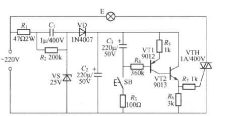
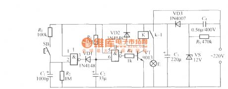
Delay light circuit with TRIAC(3)
Published:2011/4/20 2:43:00 Author:Nicole | Keyword: Delay light, TRIAC
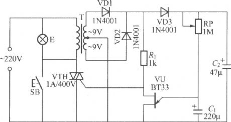
The circuit is as shown, it is a delay light circuit adopts TRIAC, T uses 220V/9V×2、3VA small transformer, there is no special requirements about other components. (View)
View full Circuit Diagram | Comments | Reading(1797)
Variable quartz crystal oscillator (VXO) circuit
Published:2011/4/20 1:19:00 Author:Ecco | Keyword: Variable , quartz crystal , oscillator , VXO
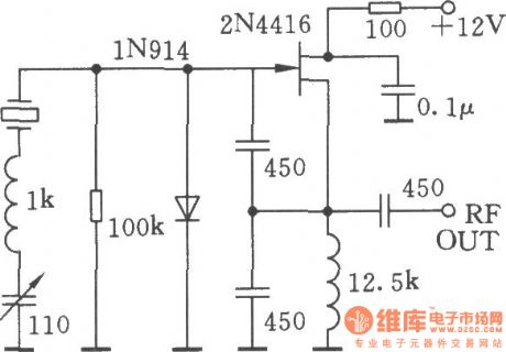
The chart shows two typical VXO circuits, in fact they arePierce circuits,the difference is theconnection.
(View)
View full Circuit Diagram | Comments | Reading(2768)
The low-frequency FM generator composed of two NE566V
Published:2011/4/20 1:46:00 Author:Ecco | Keyword: low-frequency, FM , generator
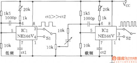
The chart shows the low-frequency FM generator composed of two NE566V. In the chart, ICl NE566Vis used for the modulation signal, IC2 works in the carrier signal. Selection ofCtlcan ensurethe modulation frequency range, selection of Ct2 could determine the center frequency of the carrier, output modulation can be used to select the square wave and triangular wave by Sl, it can realize square wave modulation and triangular wave frequency modulation.
(View)
View full Circuit Diagram | Comments | Reading(852)
Alternating polarity pulse width modulator(555)
Published:2011/4/20 1:45:00 Author:Ecco | Keyword: Alternating , polarity, pulse width , modulator, 555
View full Circuit Diagram | Comments | Reading(765)
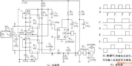
500Hz signal generator
Published:2011/4/20 3:06:00 Author:Ecco | Keyword: 500Hz , signal generator
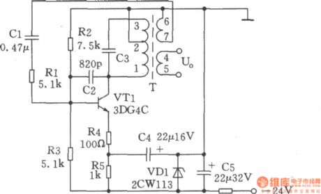
1. Specifications (1) operating frequency: 500Hz ± 10Hz; (2) Output Level: 0 ± 2.6dB (3) Output impedance: ≤ l0Ω. 2. Working principle of the circuit is shown as the circuit. 500Hz oscillator consists of VTl, T, VDl and resistors, capacitors and other components. Oscillation frequency is decided by the parallel resonant frequency of C3, L1-3, the resistor Rl is used to increase the input impedance of transistor VTl and reduce the impact of the oscillation tank. R2, R3 are DC bias resistors. R4, R5 are the emitter resistors of VTl, R4 has a current negative feedback. In order to adapt the changes of supply voltage (± 10%), it makes voltage stabilization on the both ends VT1. Under normal circumstances, L4-5 output level 0dB is ± 2.6dB/600Ω, oscillation frequency is 500Hz signal. In order to facilitate detection, the DC operating point is as follows: 'VTl the Vce = l2V ± 1V.
(View)
View full Circuit Diagram | Comments | Reading(652)
Delay light circuit with digital circuit(2)
Published:2011/4/20 2:12:00 Author:Nicole | Keyword: delay light, digital circuit
The figure is as shown, it is a delay light circuit adopts 2 input terminals and negation gate digital IC, VD3、VS、 C3、C4 form a simple capacity depressurization half wave rectifier steady voltage circuit, after connecting to power supply, two terminals of C3 will output about 12V stable DC voltage to provide the whole controller. Gate Ⅰ, gate Ⅱ, can adopt two good NAND gates of CD4011 digital IC, the input terminals of another NAND gates should be connected to ground, to avoid interference. K uses JZC-22F、DC12V small middle power electromagnetic relay. (View)
View full Circuit Diagram | Comments | Reading(568)
First-order active phase shift oscillator(F007)
Published:2011/4/20 2:32:00 Author:Ecco | Keyword: First-order, active, phase shift , oscillator
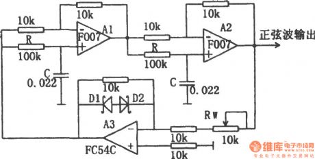
The chart shows the first-order active phase shift oscillator. In the circuit, A1 and A2 form the first order active phase shifter, and they form loops with A3. A3 is the inverting proportion amplifier, it has the effect of primary amplification, the gain adjustment is -l, the phase shift is π. D1, D2 are the regulator 2DW7C, they play the role of steady increase. According the conditions required for the oscillation, transmission coefficient | β | of the first order active phase shifter is 1. When the total phase shift is π, the circuit can oscillate, the oscillation frequency: f0 = 1/2πRC.
(View)
View full Circuit Diagram | Comments | Reading(806)
Delay light circuit with digital circuit(3)
Published:2011/4/20 1:56:00 Author:Nicole | Keyword: delay light, digital circuit
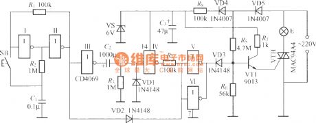
The figure is as shown, it is a practical delay light circuit, it can be used in nightstand. The feature of it is to press the key SB, the light on; press it again, the light off; if it does not press SB after the light on, the light will delay few minutes, then the light off automatically; after the light off, if you press switch two times constantly, the light will on again. This delay light is convenient to work, and it can add spices. According to T=0.639R3C2, we can obtain the delay time, but the C2 has electricity leakage, so the delay time is increased to 30~50min. (View)
View full Circuit Diagram | Comments | Reading(543)
High-performance quadrature sine wave oscillator
Published:2011/4/20 2:14:00 Author:Ecco | Keyword: High-performance , quadrature , sine wave , oscillator
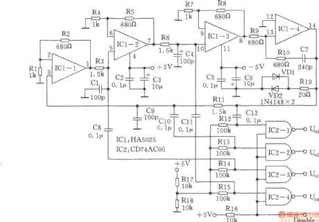
Many RC oscillators use advanced circuit in phase shift unit. It uses a voltage feedback amplifier, of which the gain will get a sharp decline in a higher frequency and stop oscillation before reaching the desired frequency. That is the reason why voltage feedback amplifier has poor phase characteristics. The RC oscillator composed of high-frequency IC HA5025 with four current-feedback amplifiers will produce four sine waves. The circuit is shown as the chart. CD74AC00 has four NAND gates, when the threshold is bias, four independent amplifiers of HA5025 produce four sine waves, sine wave AC coupled into the input which is used as a sine / square wave converter.
(View)
View full Circuit Diagram | Comments | Reading(2884)
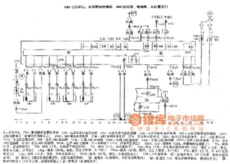
Passat ABS circuit
Published:2011/4/20 2:57:00 Author:Jessie | Keyword: ABS
View full Circuit Diagram | Comments | Reading(1676)
Single-junction transistor sine wave oscillator
Published:2011/4/20 2:22:00 Author:Ecco | Keyword: Single-junction, transistor , sine wave , oscillator

The single-junction transistor is often used in sawtooth generator and pulse generator, but it may also constitute a simple sine wave generator circuit. As an scillator circuit with discrete components, it uses few components. Circuit is shown as the chart. And comparing with ordinary unijunction relaxation oscillator circuit, it adds a LC tuned circuit to the second base, the tuned circuit generates sinusoidal oscillation depended on the driving of unijunction excitation current pulse. Adjusting resistor Rl can control the size of the current pulse, sine wave can be obtained at B2. According to the parameters of figure, the oscillation frequency is 3750Hz, the peak value of output voltage peak is 2V.
(View)
View full Circuit Diagram | Comments | Reading(4027)
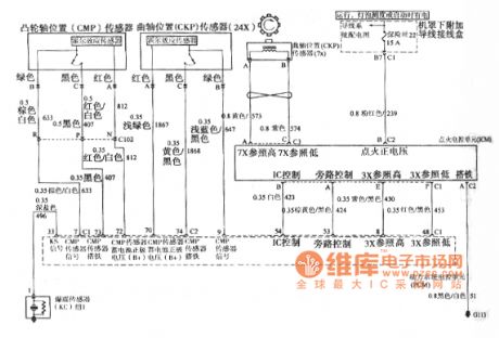
Buick GL8 camshaft position CMP sensor, crankshaft position CKP sensor, ignition electronic control unit ICM circuit
Published:2011/4/20 2:47:00 Author:Jessie | Keyword: camshaft position CMP sensor, crankshaft position CKP sensor, ignition electronic control unit ICM
View full Circuit Diagram | Comments | Reading(666)
| Pages:2052/2234 At 2020412042204320442045204620472048204920502051205220532054205520562057205820592060Under 20 |
Circuit Categories
power supply circuit
Amplifier Circuit
Basic Circuit
LED and Light Circuit
Sensor Circuit
Signal Processing
Electrical Equipment Circuit
Control Circuit
Remote Control Circuit
A/D-D/A Converter Circuit
Audio Circuit
Measuring and Test Circuit
Communication Circuit
Computer-Related Circuit
555 Circuit
Automotive Circuit
Repairing Circuit