
Circuit Diagram
Index 2056
Long time delay timing circuit with CD4541
Published:2011/4/19 22:43:00 Author:Jessie | Keyword: Long time delay, timing
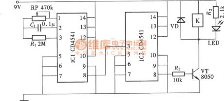
The two pieces of CD4541 can compose a long time delay timing circuit. Its delay time can reach 10 h, even several days or months. Its composition is as shown. (View)
View full Circuit Diagram | Comments | Reading(6505)
Adjustable circulating timing controller circuit
Published:2011/4/19 22:53:00 Author:Jessie | Keyword: Adjustable, circulating timing controller
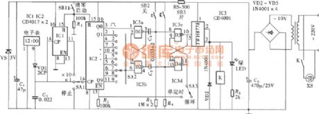
The timing controller uses the LCD's minute signals. After the combination oftwo level separate frequency circuit, it can build a multi-level timing control function. It composes single timing open/shut or automatic cycle working mode by the control switch. Control time from1 ~ 90min is adjustable. Circuit's components areas shown. (View)
View full Circuit Diagram | Comments | Reading(1033)
Atlanta electromagnetism circuit
Published:2011/4/20 1:33:00 Author:Jessie | Keyword: electromagnetism
View full Circuit Diagram | Comments | Reading(768)
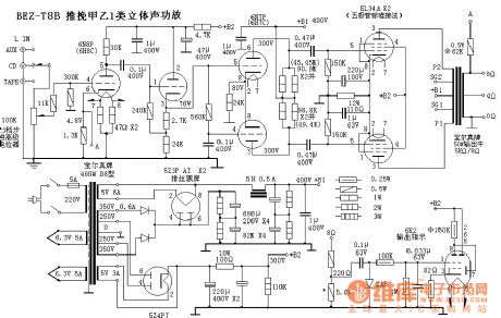
Push-pull AB class 1 stereo amplifier BEZ-T8B circuit
Published:2011/4/20 1:32:00 Author:Jessie | Keyword: AB class 1, stereo amplifier
View full Circuit Diagram | Comments | Reading(1210)
LC172 acousto-optic dual control 4-phase pulse distribution color lamp control circuit
Published:2011/4/20 0:24:00 Author:Nicole | Keyword: acousto-optic dual control, 4-phase pulse, color lamp
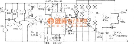
The circuit is as shown. It is composed of audio amplifier, acousto-optic dual control switch, light control circuit and AC depressurization rectifier circuit. 4-phase pulse distribution light control special IC LC172 is made as the core to consist the light control circuit. (View)
View full Circuit Diagram | Comments | Reading(649)
Touch music color lamp circuit(BH-SK-I)
Published:2011/4/19 22:39:00 Author:Nicole | Keyword: music color lamp
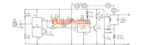
The circuit is as shown. It is composed of touch switch, SCR trigger circuit, music phonation circuit and AC depressurization rectifier circuit. BH-SK—I(IC1) is a sound control IC, it uses internal bistable state trigger as switch, to control the color lamp on or off. When the sheetmetal M is touched, the body inductive clutter singals are added to input terminal I foot of IC1 amplifier, after the singals are enlarged and shaped, selected frequency, triggered bistable state trigger by IC1, its 12 foot will output about 5V high level. This high level jumping singal outputs two roads: one is added to VT1, then VT1, VS turn on, to light up the color lamp series H1~Hn; the other is added to the trigger terminal TG of IC2 by R4, to make the trigger phonate. (View)
View full Circuit Diagram | Comments | Reading(774)
AC color lamp control circuit composed of LC181 audio modulation color lamp control chip
Published:2011/4/19 21:56:00 Author:Nicole | Keyword: AC color lamp, control chip
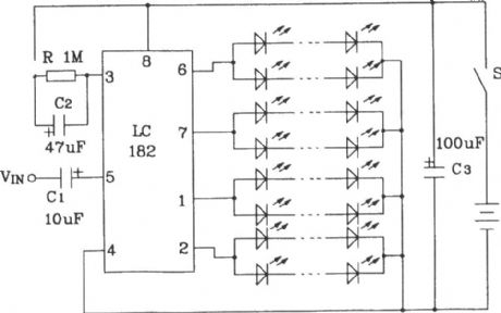
The cycle frequency is 0.5~1Hz. LED cycles flashing slowly. When connected the audio modulation singal, the cycle speed of LED will change with the audio singal, if the cycle frequency is 1Hz, then the highest modulation rate is more than 15 times. To change the value of RC, it can change the cycle speed without modulation singal. This circuit is suitable for all kinds of artwares, vases, painted screen and so on. (View)
View full Circuit Diagram | Comments | Reading(595)
Incandescent lamp life extension switch circuit(5)
Published:2011/4/19 21:43:00 Author:Nicole | Keyword: incandescent lamp, life extension

The figure is as shown, it is another connection way of the incandescent lamp life extension switch, it has two functions: one is it can start up with half wave depressurization when it is connected to the power supply, then it will turn into total pressure feeding after the filament preheats enough; the other is this circuit will transfer to half wave depressurization feeding automatically, once the mains power network voltage is 20V higher than the 220V standard voltage, it can delay the service life of incandescent lamp effectively. (View)
View full Circuit Diagram | Comments | Reading(896)
Showcase or bulletin board timing light controllor circuit (2)
Published:2011/4/19 20:35:00 Author:Nicole | Keyword: showcase or bulletin board, timing light, controllor
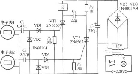
The figure is as shown, it is a showcase or bulletin board timing light controllor adopts two electronic tables control, the electronic table 1 is used to set everyday lighting up time, the electronic table 2 is used to set everyday turn-off light time. K uses small middle power electromagnetic relay such as JZC-22F、DC12V, the maximum load of contact is 5A. (View)
View full Circuit Diagram | Comments | Reading(866)
Timer circuit with monostable free sending device
Published:2011/4/19 20:27:00 Author:Nicole | Keyword: timer, free sending device

The feature of this circuit is the input terminal has anti-interference protection measures, to avoid wrong actions due to the interference signal. Besides, the time process is finished before switch S off, it can increase the reliability. (View)
View full Circuit Diagram | Comments | Reading(574)
Wideband square wave signal generator composed of CD4046
Published:2011/4/19 22:24:00 Author:Ecco | Keyword: Wideband , square wave , signal generator
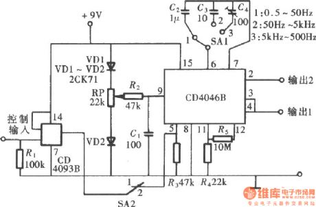
CD4046 operating frequency is up to 1MHz, it is set by parameters of external RC, it can form a wide band square wave signal generator, the circuit is as shown.
(View)
View full Circuit Diagram | Comments | Reading(5387)
KONES AV9092 amplifier remote control circuit
Published:2011/4/2 4:16:00 Author:may | Keyword: KONES, amplifier, remote control
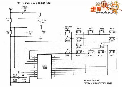
View full Circuit Diagram | Comments | Reading(1199)
High speed bridge mode driver circuit
Published:2011/4/2 4:13:00 Author:may | Keyword: High speed, bridge mode driver
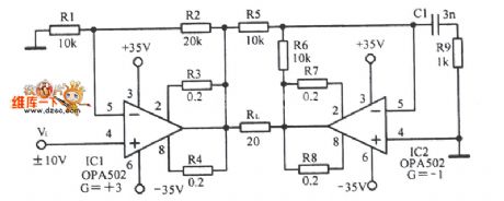
High speed bridge mode driver circuit is shown in the following picture:
(View)
View full Circuit Diagram | Comments | Reading(503)
Drive circuit diagram based on a bridge type motor
Published:2011/4/2 4:24:00 Author:may | Keyword: drive, bridge type motor
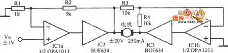
Based on a kind of Mazda driver circuit is show in the following picture:
(View)
View full Circuit Diagram | Comments | Reading(453)
America TDMA application circuit composed of RF2162
Published:2011/4/2 4:22:00 Author:may | Keyword: America TDMA
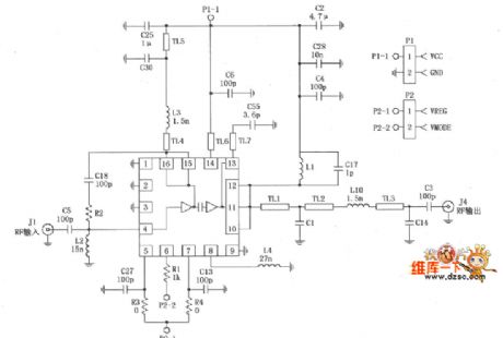
RF2162 constitutive America TDMA application circuit is show in the following picture:
(View)
View full Circuit Diagram | Comments | Reading(1354)
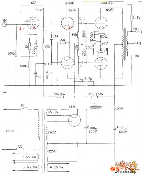
2A3A Vacuum Tube Push-Pull Amplifier Circuit
Published:2011/4/1 2:44:00 Author:may | Keyword: Vacuum Tube, Push-Pull Amplifier
View full Circuit Diagram | Comments | Reading(867)
STK4121-2 Power Amplifier Circuit Diagram
Published:2011/4/1 2:44:00 Author:may | Keyword: Power Amplifier
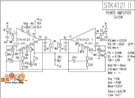
The STK4121-2 Power Amplifier Circuit Diagram is shown in the following picture:
(View)
View full Circuit Diagram | Comments | Reading(5004)
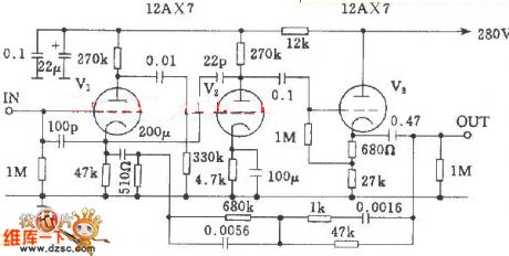
Mamn C22 electron tube equalizer amplifier circuit diagram
Published:2011/4/2 4:28:00 Author:Nicole | Keyword: Mamn, electron tube, equalizer amplifier
View full Circuit Diagram | Comments | Reading(1980)
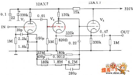
McIntosh 7 electron tube equalizer amplifier circuit diagram
Published:2011/4/2 4:28:00 Author:Nicole | Keyword: McIntosh, electron tube, equalizer amplifier
View full Circuit Diagram | Comments | Reading(1632)
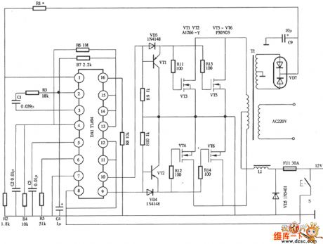
High power regulator inverter power supply circuit diagram
Published:2011/4/2 4:27:00 Author:Nicole | Keyword: regulator, inverter power supply
View full Circuit Diagram | Comments | Reading(1028)
| Pages:2056/2234 At 2020412042204320442045204620472048204920502051205220532054205520562057205820592060Under 20 |
Circuit Categories
power supply circuit
Amplifier Circuit
Basic Circuit
LED and Light Circuit
Sensor Circuit
Signal Processing
Electrical Equipment Circuit
Control Circuit
Remote Control Circuit
A/D-D/A Converter Circuit
Audio Circuit
Measuring and Test Circuit
Communication Circuit
Computer-Related Circuit
555 Circuit
Automotive Circuit
Repairing Circuit