
555 Circuit
Index 24
555 trigger and long time delay circuit
Published:2011/6/12 10:58:00 Author:nelly | Keyword: trigger, long time delay
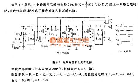
As shown on the figure 6-7, this circuit adopts the dual time base circuit 556. The half of the 556 and R,C make up of a monostable delay circuit and putting it to cascade. Then the trigger and long time delay circuit will be constructed. According to the program, we need to design the every delay time: td=1.1RC. If R1=R2=R3=R4=R, C1=C2=C3=C4=C, the total delay time: T4=4td=4.4RC. If it has n grades, Tn=1.1nRC.
(View)
View full Circuit Diagram | Comments | Reading(1351)
555 Sine wave Generator Circuit
Published:2011/6/23 22:39:00 Author:Zoey | Keyword: 555sine wave, generator, circuit
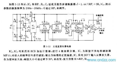
As shown in the figure 5-13, the astable multivibrator is composed of IC1, Rp1, R6 and C3, and f=1.44/(RP1+2R5)C3. Oscillation frequency of the parameter in the figure is 20Hz~20khz, which can be adjusted by RP1.
Figure5-13 Sina wave Generator Circuit
Both IC2 and IC3 use Double BCD up counter for obtain four-stage cascaded frequency. IC4 is a new switched-capacitor filter, it filters the frequency signal sent and output standard sine fundamental. While IC5 uses JEFT to input theoperational amplifier, which is used to butter the amplifier stage, and the value of amplitude can be adjusted by RP2, the magnification K≈RP2/RHo. (View)
View full Circuit Diagram | Comments | Reading(2755)
Crystal oscillator Circuit composed of 555
Published:2011/6/23 21:48:00 Author:Zoey | Keyword: Crystal oscillator, Circuit, composed of 555
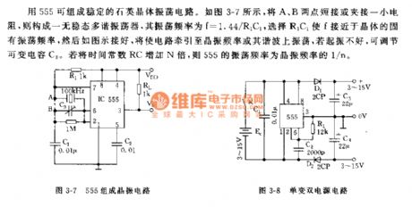
With the composition of a 555 circuit, a quartz crystal oscillator circuit can be formed. As shown in the figure 3-7, after jointing point A and point B or clamping and jointing a small resistance, an astable multi-vibrator is formed and its oscillation frequency f is 1.44/R1C1. Choose a fixed R1C1 oscillation frequency close to f, and then joint the different parts as shown in the picture, tract the circuit to crystal oscillator or to its oscillator on the harmonic. If it does not starts-up well, we can adjust the variable capacitor. If the time constant is multiplied N times, the oscillator frequency will turn to be 1/N of the crystal oscillator frequency.
(View)
View full Circuit Diagram | Comments | Reading(3241)
555 Photosensitive oscillator circuit
Published:2011/6/27 3:08:00 Author:Zoey | Keyword: 555 Photosensitive oscillator, circuit
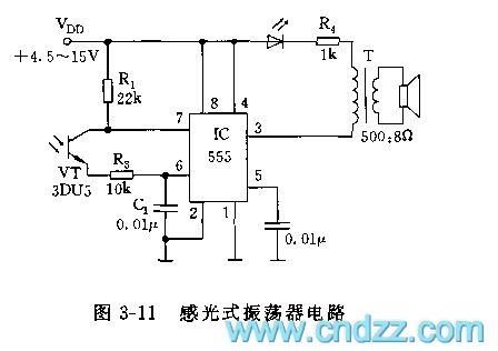
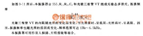
As shown in picture 3-11, this oscillator constitutes an astable multi-vibrator along with a 555, R1, R3, C1 and a photosensitive audion, and its oscillation frequency can be calculated by this formula:
f=1.44/(R+2RVT+2R3)C1
The internal resistance in photosensitive audion VT changes as light change. When exposed in a strong light, is will have a low resistance, vice versa. Therefore, the oscillation frequency changes as sensitivity of light changes, oscillation frequency can change from 1Hz to 6.5Hz.
This oscillator can be used as the leader to explore the way for the blind people, or as the harbinger of dawn or can be used in other situations. (View)
View full Circuit Diagram | Comments | Reading(800)
555 Square wave Generator with a Large-scale Changeable Duty cycle
Published:2011/6/30 0:04:00 Author:Zoey | Keyword: 555 quare wave Generator, Large-scale Changeable, Duty cycle
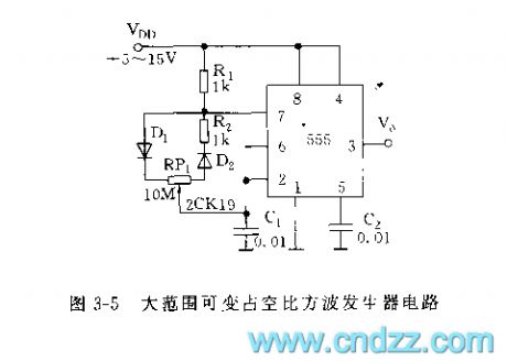
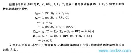
Figure 3-5 Square wave Generator Circuit with a Large-scale Changeable Duty cycle
As shown in the figure 3-5, 555, R1,R2, RP1, D1,D2 and C1 constitute an astable multi-vibrator. D1 and D2 refer to the guide tubes on the charge and discharge loop respctively.
tc=0.693(R1+RPleft)C1
td=0.693(R2+RPright)C1
t=tc+td
=0.693(R1+R2+RP)C1
Dmin=tc/T=(R1+R2+RP)≈0.01%
Dmax=tc/T=(R1+RP)(R1+R2+RP)
≈99.99%
From the formula above we can conclude that, no matter how RP1 is adjusted to, the oscillation period won't be affected. Oscillation frequency of the parameter in the figure is about 20Hz.
(View)
View full Circuit Diagram | Comments | Reading(958)
The Guangzhou Honda fixed speed cruise control circuit
Published:2011/6/30 20:33:00 Author:qqtang | Keyword: Guangzhou Honda, fixed speed, cruise control circuit
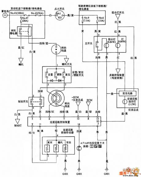
The Guangzhou Honda fixed speed cruise control circuit is shown in the circuit.
(View)
View full Circuit Diagram | Comments | Reading(687)
Southeast Soveran 4G64 engine electronic control system circuit
Published:2011/6/30 10:53:00 Author:John | Keyword: engine, electronic control system
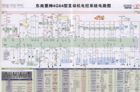
View full Circuit Diagram | Comments | Reading(2584)
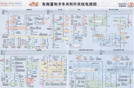
Southeast Soveran body attachment circuit
Published:2011/6/30 10:34:00 Author:John | Keyword: body attachment
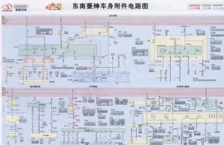
View full Circuit Diagram | Comments | Reading(669)
Audi charging system circuit
Published:2011/6/30 10:32:00 Author:John | Keyword: charging system
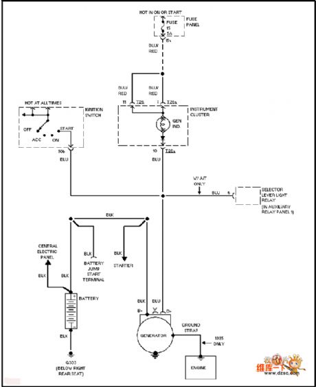
View full Circuit Diagram | Comments | Reading(984)
Audi (front drive) anti-lock braking circuit
Published:2011/6/30 10:34:00 Author:John | Keyword: anti-lock
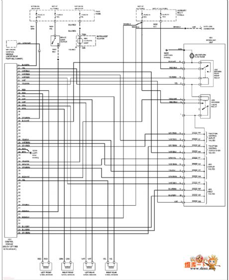
View full Circuit Diagram | Comments | Reading(685)
Southeast Soveran power window and sunroof window circuit
Published:2011/6/30 10:32:00 Author:John | Keyword: power window, sunroof window
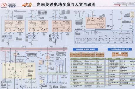
View full Circuit Diagram | Comments | Reading(764)
Audi gated light basic circuit
Published:2011/6/30 10:30:00 Author:John | Keyword: gated light
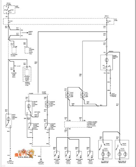
View full Circuit Diagram | Comments | Reading(722)
Southeast Soveran automatic transmission circuit
Published:2011/6/30 10:29:00 Author:John | Keyword: automatic transmission
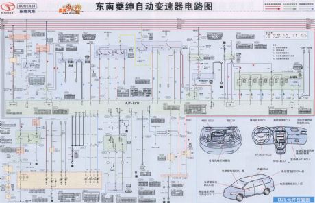
View full Circuit Diagram | Comments | Reading(686)
Audi interior light circuit
Published:2011/6/30 10:28:00 Author:John | Keyword: interior light

View full Circuit Diagram | Comments | Reading(808)
Southeast Lioncel automatic transmission, ABS, airbag and anti-theft system schematic
Published:2011/6/30 10:28:00 Author:John | Keyword: automatic transmission, ABS, airbag, anti-theft system
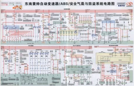
View full Circuit Diagram | Comments | Reading(1099)
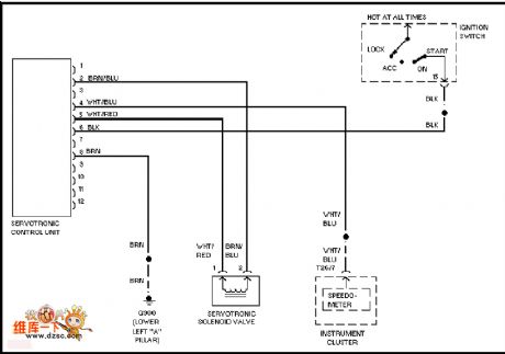
Audi electronic power steering circuit
Published:2011/6/30 10:26:00 Author:John
View full Circuit Diagram | Comments | Reading(2334)
Audi (with DRL) fog lamp circuit
Published:2011/6/30 10:25:00 Author:John | Keyword: fog lamp

View full Circuit Diagram | Comments | Reading(829)
Southeast Freeca body attachment system circuit
Published:2011/6/30 10:24:00 Author:John | Keyword: body, attachment system
View full Circuit Diagram | Comments | Reading(760)
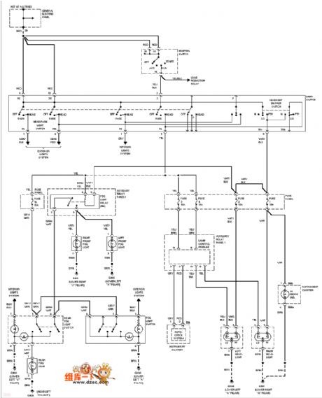
Audi (without DRL) headlamp and fog lamp circuit
Published:2011/6/30 10:23:00 Author:John | Keyword: headlamp, fog lamp
View full Circuit Diagram | Comments | Reading(858)
Phase sequence with phase loss detection circuit
Published:2011/6/30 10:21:00 Author:John | Keyword: Phase sequence, phase loss
View full Circuit Diagram | Comments | Reading(1999)
| Pages:24/47 At 202122232425262728293031323334353637383940Under 20 |
Circuit Categories
power supply circuit
Amplifier Circuit
Basic Circuit
LED and Light Circuit
Sensor Circuit
Signal Processing
Electrical Equipment Circuit
Control Circuit
Remote Control Circuit
A/D-D/A Converter Circuit
Audio Circuit
Measuring and Test Circuit
Communication Circuit
Computer-Related Circuit
555 Circuit
Automotive Circuit
Repairing Circuit