
555 Circuit
Index 37
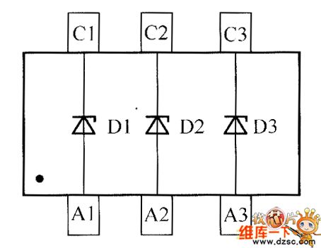
Field-effect transistor RTF010P02、RTF011P02、RTF015P02 internal circuit
Published:2011/6/5 4:16:00 Author:John | Keyword: Field-effect transistor
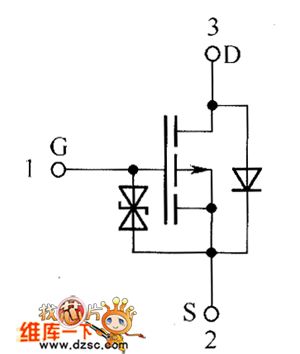
Field-effect transistor RTF010P02、RTF011P02、RTF015P02 internal circuit is shown below.
(View)
View full Circuit Diagram | Comments | Reading(754)
The powersaver circuit of 555 fridge
Published:2011/5/27 0:48:00 Author:Borg | Keyword: powersaver circuit
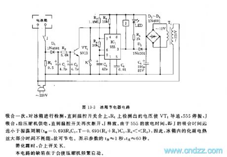
Customers often pay attention to the reduced power consumption of the fridge while its functions are not effected. The circuit shown in Figure 13-3 is applied in all types of two-door fridges, under the condition of not changing its internal control circuits, it can cut off the defrost heating wire in the fridge and save the power.The circuit consists of step-down rectifier circuit, test switch and oscillating control circuit,etc. 555,R2,R4 and C3 form the controllable oscillator, and the oscillator is under the control of the switch tube VT1. When VT1 is conducting, the 4-pin of 555 is in a low LEV and it stops oscillating.
(View)
View full Circuit Diagram | Comments | Reading(1794)
The internal lighting lamp state test circuit of 555 fridge
Published:2011/5/27 0:11:00 Author:Borg | Keyword: internal lighting lamp, test circuit
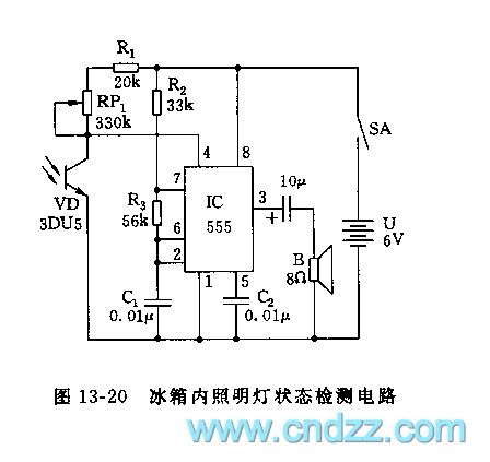
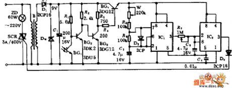
555, R2,R3 and C1 consist a coercive multi-oscillator, the 4-lead of the coercive terminal links to the C terminal of LED 3DU5, under the light, 3DU5 is in a low resistance, so the 4-lead of 555 is in a low LEV and it is forced to be reset, the oscillator stops working and the loudspeaker is quiet; when there is no light, 3DU is blocked and its resistance is high, the 4-lead is in a high LEV, the 555 oscillator is starting to work and it frequency is f=1.44/(R2-2R3)C1The shaking frequency of the parameter in the figure is 993Hz.
Figure 13-20 The internal lighting lamp state test circuit of the fridge (View)
View full Circuit Diagram | Comments | Reading(936)
555 adjustable timer circuit for hours
Published:2011/6/2 4:01:00 Author:nelly | Keyword: adjustable timer
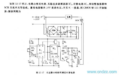
As shown in the figure 12-17, the circuit is composed of rectifier circuit, actable multivibrator IC1, count circuit IC2, unijunction oscillator and SCR AC switch. The rectifier circuit outputs 10V DC voltage, once the switch K is turned on, the CMOS type 555 starts to oscillate.
The oscillation frequency can be changed by adjusting RP1, it is continuously tunable from 0.1~1Hz.
IC2(CC4040) is a 12 bit binary serial counting/frequency divider. When the switch K is closed, due to the voltage of C9 can not suddenly changed, R terminal(11 foot) has a positive peak pulse voltage, it puts each trigger of CC4040 integrated block on 0 .
(View)
View full Circuit Diagram | Comments | Reading(1519)
555 Bootstrap Voltage Sawtooth Wave Generator Circuit
Published:2011/5/19 17:57:00 Author:Robert | Keyword: Bootstrap Voltage, Sawtooth Wave, Generator
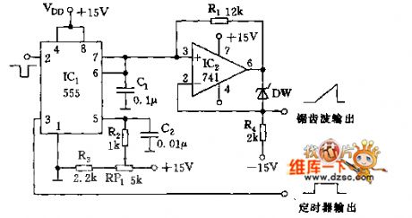
As shown, the sawtooth generator is made up by the 555 monostable timing circuit and feedback bootstrap circuit.
The IC2 (LM741) operational amplifier is used as feedback bootstrap circuit. The 6 foot's output voltage would supply the sawtooth voltage's charging current for C1 through R1. The current size depends on the voltage regulator tube DW's clamp size and the resistance value of R1, which would change the sawtooth's cycle time and oscillation amplitude.
(View)
View full Circuit Diagram | Comments | Reading(2700)
Toyota Vios automatic transmission control circuit
Published:2011/5/23 21:50:00 Author:John | Keyword: automatic transmission
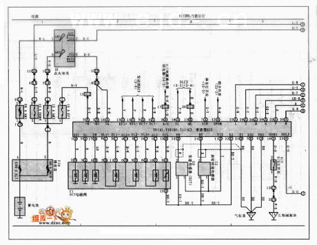
Toyota Vios automatic transmission control circuit is shown below.
(View)
View full Circuit Diagram | Comments | Reading(3666)
Toyota Vios ABS control circuit
Published:2011/5/23 21:04:00 Author:John
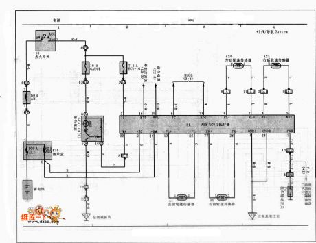
Toyota Vios ABS control circuit is shown below.
 (View)
View full Circuit Diagram | Comments | Reading(4334)
crystal diode DDZX6V8CTS internal circuit
Published:2011/5/24 1:03:00 Author:John | Keyword: crystal diode

Crystal diode DDZX6V8CTS internal circuit is shown below.
(View)
View full Circuit Diagram | Comments | Reading(584)
Street light timing circuit
Published:2011/5/24 2:19:00 Author:John | Keyword: Street light
This circuit shows that light control timing lights can automatically open in the evening for several hours and automatically off afterwards.
When darkness comes, under the action of the photoelectric switch, BG4 conducts. And oscillator circuit constituted by IC1 lamp begins to vibrate with constant IC 3 output pulse. As charging time constant of C3 is large and the oscillation period of oscillation circuit is T < <R7C3, the voltage at the starting moment for C3 is 1/3Vcc. The number 3 output end of IC is in high power level. As a result, bidirectional thyristor SCR is triggered to turn on and both ends of bulb ZD is energized to light.
(View)
View full Circuit Diagram | Comments | Reading(1243)
crystal diode DDZX7V5CTS internal circuit
Published:2011/5/24 0:59:00 Author:John | Keyword: crystal diode

Crystal diode DDZX7V5CTS internal circuit is shown below.
(View)
View full Circuit Diagram | Comments | Reading(606)
Toyota Vios airbag control circuit
Published:2011/5/23 20:15:00 Author:John | Keyword: airbag

Toyota Vios airbag control circuit is shown below.
(View)
View full Circuit Diagram | Comments | Reading(2416)
Battery thermocouple protection circuit
Published:2011/5/19 0:42:00 Author:John | Keyword: thermocouple
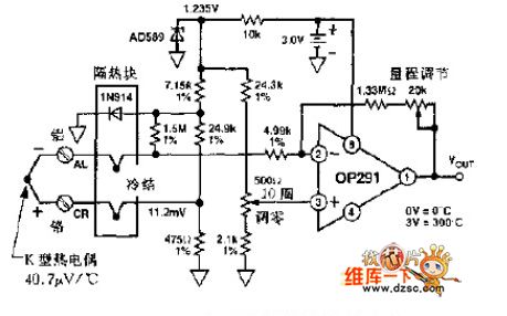
K-type thermocouple is placed in insulation terminal block and the ambient temperature of the thermocouple is continuously controlled by 1N914 diode. Diode voltage can modify Thermal EMF on the junction force through feedback of small voltage regulator. Thermal EMF would be sent through to amplifier by 1.5MΩ and 475Ω. During the calibration, the thermocouple junction should be placed in the freezing cold water. Adjust 500Ω to ensure the output pressure of zero. Then insert thermocouple into the 250 ℃ furnace and adjust range for the output of 2.50V. In the range of 0 ~ 250 ℃, the accuracy for the K-type thermocouple is ± 3 ℃.
(View)
View full Circuit Diagram | Comments | Reading(3081)
Electronic Mouse Killer (5)
Published:2011/5/16 4:44:00 Author:Sue | Keyword: Electronic, Mouse Killer
When a mouse touches the sensor between A,B, V1 and V2 will be connected and C3 begins to charging. When the voltage reaches a certain level, V3 and V4 will be connected, making K connected, and the alarm circuit and high voltage output circuit begin to work. IC will output music signals, which will drive BL to make a warning sound. The other circuit will send the alarm signal through W, which can be received by the users within 1km with a FM radio. At the same time, VL1 and VL2 are illuminated, high voltage generator begins to oscillate and generate a pulse high voltage, which will kill the mouse. (View)
View full Circuit Diagram | Comments | Reading(1806)
The circuit of Chevrolet-Lumina 2.2L
Published:2011/5/17 6:32:00 Author:Borg | Keyword: Chevrolet-Lumina, circuit
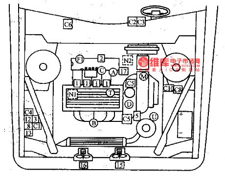
The Lumina produced by Chevrolet of GM,USA, is fixed with 4-cylinder water cooling petrol engine, whose emission is 2.2L, and computer control multiple points (4 injecters) inject fuel at the same time, the admission in under control. The components layout is shown in Figure 7-1.
Figure 7-1 the component layout of Lumina 2.2LComputer equipment: C1-chief computer; C2-detection plug; C3-fault indicator; C4-oil pump/ computer fuse; C5-computer ground connection; C6-fuse box; C8-power supply center on the left of the engine (View)
View full Circuit Diagram | Comments | Reading(1181)
Temperature Frequency Conversion Circuit Composed Of 555 And Precise Temperature Sensor
Published:2011/5/17 8:58:00 Author:Robert | Keyword: Temperature, Frequency Conversion, Precise, Temperature Sensor

The Temperature Frequency Conversion Circuit Composed Of 555 And Precise Temperature Sensor is shown below.
(View)
View full Circuit Diagram | Comments | Reading(1331)
Internal circuit of crystal diode DDZXDDZXS
Published:2011/5/15 3:25:00 Author:John | Keyword: crystal diode DDZXDDZXS

Internal circuit of crystal diode DDZXDDZXS is shown below.
(View)
View full Circuit Diagram | Comments | Reading(591)
UC3842 Application circuit
Published:2011/5/15 2:51:00 Author:John
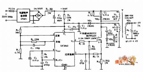
UC3842 Application circuit is shown above.
(View)
View full Circuit Diagram | Comments | Reading(16318)
Internal circuit of crystal diode DDZX9690TS
Published:2011/5/15 3:10:00 Author:John | Keyword: crystal diode DDZX9690TS
Internal circuit of crystal diode DDZX9690TS is given in the following.
(View)
View full Circuit Diagram | Comments | Reading(556)
Cadillac electric seats circuit diagram(6 setting states)
Published:2011/5/11 2:35:00 Author:Ecco | Keyword: Cadillac, electric seats, 6 setting states
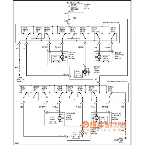
Cadillac electric seats circuit diagram(6 setting states) is shown as the chart.
(View)
View full Circuit Diagram | Comments | Reading(708)
Bicyle Bell Circuit (1)
Published:2011/5/9 3:30:00 Author:Robert | Keyword: Bicyle, Bell
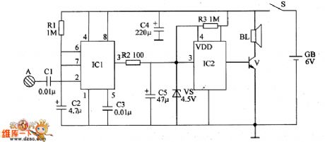
The bicycle bell circuit intruduced in this example can give the voice tone: Please make way, thank you after the touching by hands.The circuit's working principle is shown below.This bycycle bell circuit is made up by monostable trigger and voice circuit which is shown in the picture below.The monostable trigger circuit is made up by time-reference integrated circuit IC1, touching electrode A, capacitors C1~C3 and resistance R1.The voice circuit is made up by voice integrated circuit IC2, zener diode VS, resistance R2, R3, audio amplification transistor V and speaker BL.When the power switch S is connected, the monostable trigger is in stable mode. IC1's 3 foot outputs low voltage level to make the voice integrated circuit IC2's 3 foot and 4 foot be low voltage level. The transistor V is disconnected and the speaker B has no sound.When the touching electrode A is touched by hands, the human body sensing signal is transmitted to IC1's 2 foot through the capacitor C1 to trigger IC1 to change the stable mode to transient mode. Its 3 foot outputs high voltage level to make the IC2's 3 foot and 4 foot turn to be high voltage level. The transistor V is connected and speaker BL would play the voice tone.Each time the touching electrode A is touched, IC1's invert transient time would be 5s and the voice circuit would play twice the voice tone.
(View)
View full Circuit Diagram | Comments | Reading(940)
| Pages:37/47 At 202122232425262728293031323334353637383940Under 20 |
Circuit Categories
power supply circuit
Amplifier Circuit
Basic Circuit
LED and Light Circuit
Sensor Circuit
Signal Processing
Electrical Equipment Circuit
Control Circuit
Remote Control Circuit
A/D-D/A Converter Circuit
Audio Circuit
Measuring and Test Circuit
Communication Circuit
Computer-Related Circuit
555 Circuit
Automotive Circuit
Repairing Circuit