
555 Circuit
Index 33
555 digital timer circuit used in competition
Published:2011/6/3 20:14:00 Author:nelly | Keyword: digital timer, competition
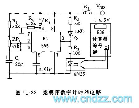
As shown in the figure 11-33, the timing circuit still uses inexpensive 838 calculator as display terminal, it is composed of second clock generator and photocoupler. It can be used in counting second occasions such as sports tournament, intelligence competition, the reading is accurate and visualized, it also has suspensive function.
The actable multivibrator is made of IC(555) and R1, RP1, C1, the oscillation frequency is f=1.443/(R1+RP1)C1, the frequency can be adjusted to 1Hz by RP1. K1, K2 are closed, then IC starts to vibrate. The 3 foot output is added to photocoupler, the isolated output is added to = key of 838 calculator. Before timing, it should operate calculator firstly, it is counted for accumulating 1, in other words, pressing ON/C key → + key → 1 key, then K1, K2 are turned on.
(View)
View full Circuit Diagram | Comments | Reading(1346)
555 multi-analogue sound generator circuit
Published:2011/6/7 4:23:00 Author:nelly | Keyword: multi-analogue sound, generator
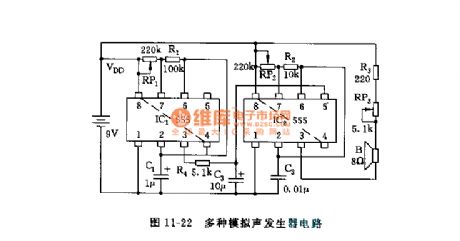
As shown in the figure 11-22, the circuit is composed of two 555 and some resistor capacitor components, the astable multivibrator connsists of IC1 and RP1, R1, C1, the oscillation frequency is about 5~10Hz, it can be changed by adjusting RP1. The frequency of oscillator which is made of IC2 and RP2, R2, C2 is between 1~10kHz, it can be changed by adjusting RP2, IC2 is a controlable voltage oscillator, its control terminal 5 foot is controlled by triangular wave voltage, this triangular wave is obtained from IC1 output and then integrated by R4, C3 integration circuit. IC2's oscillation frequency changes in relation to control voltage, it will send out all kinds of analogue sound, such as cricket noise and bird sound.
(View)
View full Circuit Diagram | Comments | Reading(1333)
555 60s acousto-optic digital timer circuit used in competition
Published:2011/6/3 20:31:00 Author:nelly | Keyword: acousto-optic digital timer
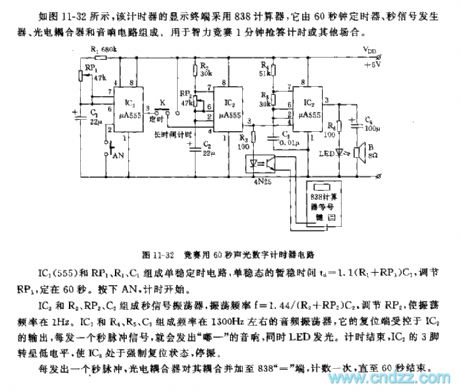
The monostable timing circuit is composed of IC1(555) and RP1, R1, C1, the monostable short stabilization time td=1.1(R1+RP1)C1, it is fixed on 60s by adjusting RP1. Pressing AN, the timing is starting.
The second signal oscillator is made of IC2 and R2, RP2, C2, the oscillation frequency is f=1.44/(R2+RP2)C2, the frequency can be 1Hz by adjusting RP2. With about 1300Hz frequency, the audio frequency oscillator consists of IC3 and R4, R5, C3, its reset terminal is controlled by IC2's output, when it sends out a second pulse signal, it will emit do sound, LED lights. After timing, IC2's 3 foot turns into low level, then IC3 is in enforced reset state, it stops to vibrate.
(View)
View full Circuit Diagram | Comments | Reading(727)
555 optical control delay flash toy car circuit
Published:2011/6/7 7:22:00 Author:nelly | Keyword: optical control, delay flash, toy car

After receiving the optical signal, this car will move straight forward, at the same time, it has red and green alternately flashing. After one minute, it stops automatically.
As shown in the figure 11-4, silicon photocell adopts 2CR33 type, after illuminated, VT1 is saturation conduction, IC1 is triggered, 3 foot is high level, VT2 turns on, J pulls in, J1-1 turns on, DC motor M operates, the car moves. IC1 is monostable delay circuit, the delay time also is the car's running time td=1.1R4C3, it is about 60s. When it is time out, 3 foot turns to low level, J releases, motor M stops running. IC1 triggers setting, simultaneously, VT3 turns on, the multivibrator which is composed of VT4, VT5 starts to vibrate, it sends out the signal of red and green alternately flashing, the period is 2s.
(View)
View full Circuit Diagram | Comments | Reading(758)
555 firing control circuit
Published:2011/6/7 7:41:00 Author:nelly | Keyword: firing control
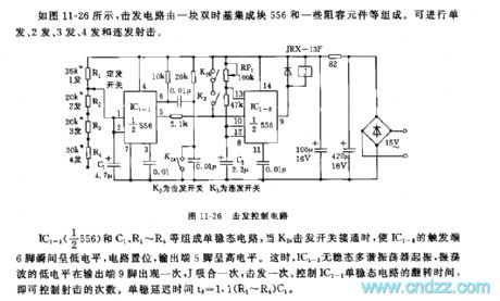
As shown in the figure 11-26, the firing circuit is composed of a double time base integrated block 556 and some resistor capacitor components. It can make single shot, 2 shots, 3 shots, 4 shots and a running fire.
The monostable circuit is made of IC1-1(1/2 556) and C1, R1~R4, when K2 fires switch to turn on, the trigger terminal 6 foot of IC1-1 turns to low level at the moment, the circuit is set, output terminal 5 foot is high level. Then IC1-2 astable multivibrator starts to vibrate, the low level of oscillatory wave turns one time in the output terminal 9 foot, J pulls in one time, J also fires one time. The frequency of shoot can be controlled by the reversal time of IC1-1 monostable circuit. The monostable delay time td=1.1(R1~R4)C1.
(View)
View full Circuit Diagram | Comments | Reading(1018)
555 toy light piano circuit
Published:2011/6/8 1:02:00 Author:nelly | Keyword: toy, light piano

As shown in the figure 11-24, the astable multivibrator is composed of IC(555) and R1, C1 and photosensitive resistance RG, the oscillation frequency f=1.44/(R1+2RG)C1. We can see, the oscillation frequency is related to RG, and RG changes in relation to the light intensity. If this circuit is put under the light, and the finger shakes back and forth, it will send out multi sounds.
(View)
View full Circuit Diagram | Comments | Reading(2372)
555 outburst audio circuit
Published:2011/6/7 7:59:00 Author:nelly | Keyword: outburst audio
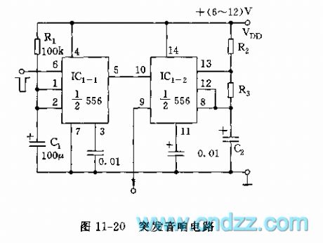
As shown in the figure 11-20, the outburst audio circuit is composed of a monostable trigger circuit and a multivibrator, it can be made of a 556 integrated block and some resistor capacitor components, it is used in audio, alarming and so on.
When a negative trigger pulse is added to IC1-1's trigger terminal 6 foot, IC1-1 rolls over and it is timed, td=1.1R1C1,the metastable time of graphical parameter is about 10s. The outputed high level pulse is added to IC1-2's reset terminal 10 foot, then IC1-2 starts to vibrate,the oscillation frequency f=1.44/(R2+2R3)C2. According to different occasions and needs, the audio frequency can be designed, after 10s, it stops automatically. This circuit also can be used to control the electrical equipments.
(View)
View full Circuit Diagram | Comments | Reading(764)
555 game machine control hand shank circuit
Published:2011/6/7 8:28:00 Author:nelly | Keyword: game machine, control, hand shank
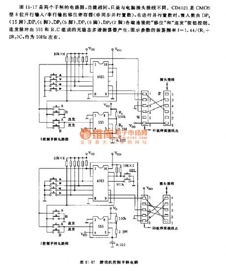
The figure 11-17 is a circuit diagram of two hand shanks, their functions are the same, but the computer plug connection is different. CD4021 is CMOS type 8 bit parallel input/serial output shift register(non-synchronous parallel set), when it is synchronous parallel seting, the seting number is controlled by shift and fusillade buttons which are connected by DP1(15 foot), DP4(4 foot), DP5(5 foot), DP6(6 foot), DP7(7 foot). The repeating pulse is produced by astable multivibrator which is composed of 555 and R, C, the oscillation frequency of the graphical parameters f=1.44/(R1+2R2)C, it is about 50Hz.
(View)
View full Circuit Diagram | Comments | Reading(1777)
555 pursual lighting controller circuit
Published:2011/6/7 8:49:00 Author:nelly | Keyword: pursual lighting, controller

As shown in the figure 11-29, the controller is composed of 4-step monostable timing circuit, it adopts interstage head-tail connecting to form ordinal trigger loop. After connected the power supply, only AN button is pressed, it can run. Each step's delay can be adjusted by its potentiometer. Such as the first step, its delay time td=1.1RP1C1,the max delay time, namely, the time of LED1 lighting is about 10s. The other steps are the same.
If this circuit is remodeled, then the output can control the on/off of TRIAC, and it also can control the colored lights, it can be used as dance party lighting cintroller or other time schedule controllers. The amount of cascade connection doesn't matter, it can form pursual loop or multicolour pattern.
(View)
View full Circuit Diagram | Comments | Reading(756)
555 automatic start type over-current protection control circuit
Published:2011/6/8 0:31:00 Author:nelly | Keyword: automatic start type, over-current protection, control

As shown in the figure 10-10, the over-current protection circuit is made as the core of 555 which is connected into R-S trigger mode. In the figure, M is the DC motor which is needed to limit current or regulate speed. 555's 6 foot(R terminal) is connected to high level, 2 foot(S terminal) is connected between M and sample resistor R4. RP1 is used to adjust the control terminal's(5 foot) voltage, namely, it adjusts the threshold voltage of R and S terminals. When it works normally, RP1 is adjusted, R4's sample voltage is lower than S terminal's threshold level, 555 is set, V1 is saturation conduction, M runs normally.
(View)
View full Circuit Diagram | Comments | Reading(2373)
555 city communication electric acousto-optical alarming circuit
Published:2011/6/8 23:40:00 Author:nelly | Keyword: city communication, electric acousto-optical, alarming
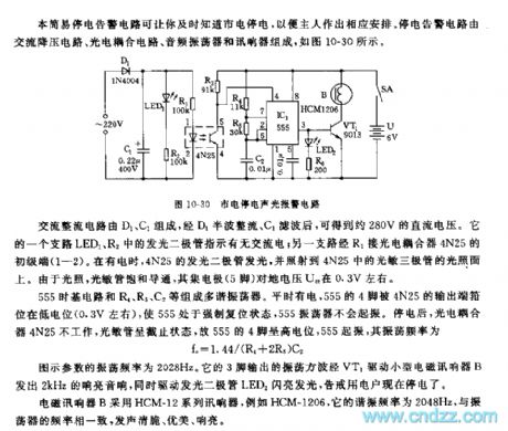
The multivibrator is composed of 555 time base circuit and R4, R5, C2. It always has electricity, 555's 4 foot is clampped to low level(about 0.3V) by 4N25's output terminal, 555 is forced in reset state, 555 oscillator does not vibrate. After power failure, the photoelectric coupler 4N25 does not work, the photosensitive tube is in off condition, so 555's 4 foot is high level, 555 starts to vibrate, the oscillation frequency fc=1.44(R4+2R5)C2.
The figured parameter's oscillation frequency is 2028Hz. Its oscillation square wave which is outputed by 3 foot sends out 2kHz sonorous sound by VT1 driving small B, at the same, it drives LED2 to flash, it warns the user that it is power failure.
(View)
View full Circuit Diagram | Comments | Reading(1067)
555 household electron protector circuit
Published:2011/6/9 8:14:00 Author:nelly | Keyword: household electron, protector

As shown in the figure 10-16, 555 obtains VDD=+12V supply voltage from hypotension rectifier circuit. 555 is in reset state, J has no action, it transmit power normally. When it is over load, the hypotension produced by RP1 increases, VT1 is saturation conduction, 2 foot is low level(<1/3VDD), 555 is reset, J pulls in, the power supply is cut off.
When the body gets an electric shock, the current of transformer T's L2, L3 is not equal, the magnetic flow produced by two coils can not be canceled out, the alternating voltage is induced by the both sides of L1, it is rectified by D3, then VT1 is saturation conduction, 555 is reset, J pulls in, the AC power supply is cut off.
(View)
View full Circuit Diagram | Comments | Reading(752)
555 high-low voltage protection delay circuit
Published:2011/6/9 8:31:00 Author:nelly | Keyword: high-low voltage, protection delay
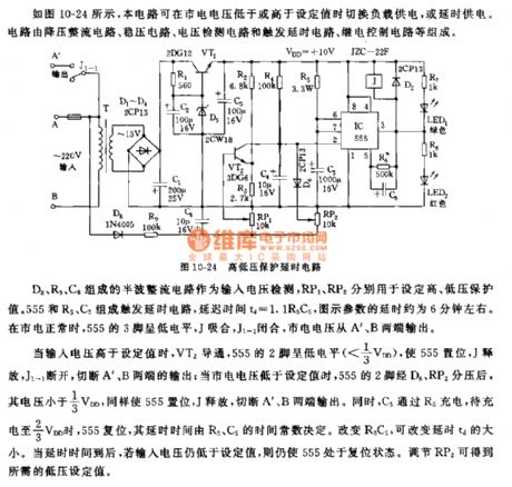
When the input voltage is higher than the set value, VT2 turns on, 555's 2 foot is low level(<1/3VDD), 555 is set, J is released, J1-1 is cut off, A, B terminals' output is cut off; when the mains voltage is lower than the set value, the voltage of 555's 2 foot is divided by D6, RP2, its voltage is lower than 1/3 VDD, then 555 is set, J is released, A, B terminals' output is cut off. At the same time, C5 is charged by R5, when it is charged to 2/3 VDD, 555 is reset, its delay time is decided by the time constant of R5, C5. The delay time td can be changed by adjusting R5C5. When it reaches the delay time, if the input voltage is still lower than the set value, then 555 is also in reset state. The needed low voltage set value can be got by adjusting RP2.
(View)
View full Circuit Diagram | Comments | Reading(2214)
555 multifunction household appliance protector circuit(1)
Published:2011/6/9 9:02:00 Author:nelly | Keyword: multifunction household appliance protector

When it comes undervoltage or overvoltage state, D2 or D1 turns on, IC's 2 foot and 6 foot are high level(>2/3 VDD), then 555 circuit is turned reset, 3 foot output is low level, relay J is released, J3, J4 are cut off, the household appliances are protected, at the same time, LED lights. The delay ON circuit is composed of C3, R4, R5 and 555, when it is turned on or instantaneous power failure, the voltage on C3 can not suddenly changed, 555's 2 foot is positive peak voltage(>2/3 VDD), then 555 is in reset state, 3 foot is low level, J has no action, socket CZ has no electricity. LED1 lights. With C3's charging, when the electric potential of 2 foot and 6 foot is lower than 1/3 VDD triggrt level, 555 is set, 3 foot is high level, J pulls in, J3, J4 are turned on, household appliance socket has electricity.
(View)
View full Circuit Diagram | Comments | Reading(950)
555 multifunction household appliance protector circuit(2)
Published:2011/6/9 9:00:00 Author:nelly | Keyword: multifunction household appliance protector
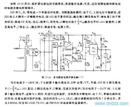
As shown in the 10-15, the protector circuit consists of AC hypotension, DC steady voltage circuit, undervoltage, overvoltage detection circuit and power-off delay circuit, relay control part.
A monostable dalay circuit is composed of 555 and C4, R4. When it is connected to power supply, due to the voltage on C4 can not suddenly changed, 555's 2 foot and 6 foot have a positive peak pulse voltage, then 555 is in reset state, output terminal 3 foot is low level, relay J is in release condition, the socket CZ has no electricity. With C4's charging, when 2 foot level is lower than 1/3 VDD triggrt level, 555 is set, 3 foot is high level, J pulls in, J1-1 adherent point is closed, the socket has electricity, the electric appliance works.
(View)
View full Circuit Diagram | Comments | Reading(1147)
555 voltage double hresholds automatical protector circuit
Published:2011/6/10 18:44:00 Author:nelly | Keyword: voltage double hresholds, automatical protector
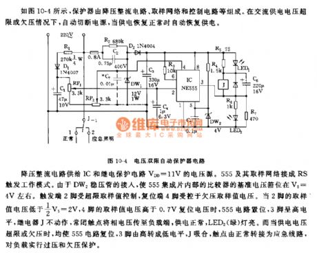
The hypotension rectifier circuit provides IC and relay protection circuit with VDD=11V voltage source. 555 and sample network are connected into RS trigger work pattern. Because DW2 is connected, the 555 integrated chip internal comparator's reference voltage is clamped in V5=4V. The terigger terminal 2 foot is controlled by transfinite sample value, the reset terminal 4 foot is controlled by undervoltage sample value voltage. When 2 foot's sample value voltage is lower than 1/2 V5=2V, 4 foot's sample value voltage is higher than 0.7V reset voltage, 555 circuit sets, 3 foot is high level, relay J has no action, normally closed contact transport the voltage to load terminal, the power supply is normal, LED2(green)lights. When the voltage power is transfinite or undervoltage, 555 circuit is reset, 3 foot turns from high level to low level, J pulls in, the contact turns to emergency line, it has overvoltage and undervoltage protection for the load.
(View)
View full Circuit Diagram | Comments | Reading(749)
555 motor integrated protection warning device circuit
Published:2011/6/10 19:13:00 Author:nelly | Keyword: motor, integrated protection, warning device
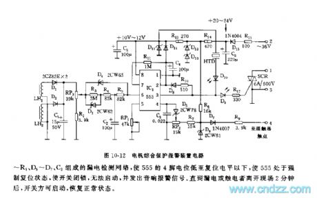
As shown in the figure 10-12, this device is made as the core of 555. It fully uses the characteristic of time base circuit's trigger set, reset and control, such as the characteristic of 555's 4 foot's reset preferentially, it is used as the input terminal of check of leak current; when it comes overload, phase failure, short trouble, it adopts 6 foot's high impedance threshold characteristic as the overcurrent protection reset terminal; it uses 5 foot's control characteristic as overcurrent protection regulation; it uses 2 foot's high impedance terigger characteristic and 7 foot's discharge characteristic as the terigger control which is needed by delay automatical recovery; it adopts 555's high driving force(can reach 200mA) to drive SCR directly. Using a 555 circuit can achieve integrated protection control.
(View)
View full Circuit Diagram | Comments | Reading(932)
555 electrical equipment overload and open-phase protection device circuit
Published:2011/6/10 19:35:00 Author:nelly | Keyword: electrical equipment, open-phase protection device
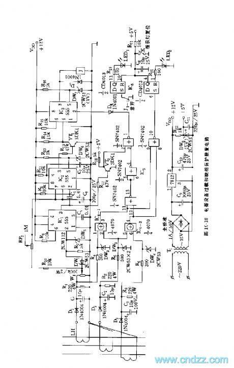
The current transformer LH couples out the current which flows the three phase proportionally, after rectificated and filtered by D1, D2, D3, C1, C2, C3, it is added to voltage comparator and phase failure protection circuit. The voltage comparator is composed of IC1 and DW1, DW5, R7, when it passes beyond the preseting voltage, DW1 is stove in, IC1's 2 foot is high level(>1/3 VDD), IC1 is reset, it outputs low level. IC2 is set by the low jumping signal, VT1 turns on, IC3 is sealed, its output is low level. At the same time, C6 is charged by R10, RP2, when C6's voltage is charged to 2/3 VDD threshold value level, IC2 is reset, 3 foot turns to low level, VT1 is cut off, IC3's 4 foot is high level, the blockage timing is ended.
(View)
View full Circuit Diagram | Comments | Reading(1030)
555 motor phase failure overload protector circuit
Published:2011/6/10 19:53:00 Author:nelly | Keyword: motor, phase failure overload, protector
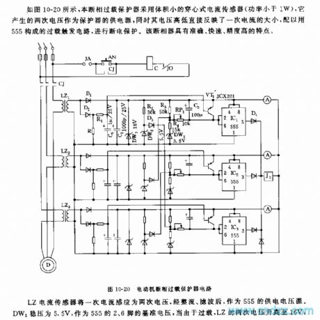
Once current can be induced into twice voltage by LZ current sensor, after rectificated and filtered, it is used as 555's voltage supply source. The DW2 steady voltage is 5.5V, it is used as the reference voltage of 555's 2 foot and 6 foot, Due to overload, LZ's twice voltage increases to 16V, when 555's 2 foot voltage is lower than 1/3 VDD, 555 is set, J0 pulls in, the contactor CJ is power failure, motor stops running, it is protected. The adjustable delay action circuit is made of RP1 and C2, on the condition of large current or long starting time when the motor works, it will avoid power failure due to the protection.
When the motor operates normal, VT1 cuts off. When the motor stops running, D2 is low level, VT1 turns on, C2 is discharged, it can prevent error actions when the motor works again.
(View)
View full Circuit Diagram | Comments | Reading(1240)
The automatical overcurrent protection circuit of 555 motor
Published:2011/6/10 20:06:00 Author:nelly | Keyword: overcurrent protection, motor
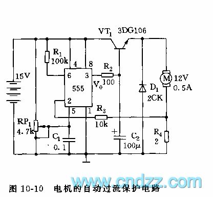
As shown in the figure 10-10, the overcurrent protection circuit is made as the core of 555 which is connected into R-S trigger pattern. In the figure, M is DC motor which is needed to limit current or regulate speed. 555's 6 foot(R terminal)connects high level, 2 foot(S terminal)is connected between M and sample resistor R4. RP1 is used to adjust the control terminal's(5 foot)voltage, namely, adjusting R terminal's and S terminal's threshold voltages. When it works normally, adjusting RP1, R4's sample voltage is lower than S terminal's threshold level, 555 is set, VT1 is saturation conduction, M operates normally.
(View)
View full Circuit Diagram | Comments | Reading(3142)
| Pages:33/47 At 202122232425262728293031323334353637383940Under 20 |
Circuit Categories
power supply circuit
Amplifier Circuit
Basic Circuit
LED and Light Circuit
Sensor Circuit
Signal Processing
Electrical Equipment Circuit
Control Circuit
Remote Control Circuit
A/D-D/A Converter Circuit
Audio Circuit
Measuring and Test Circuit
Communication Circuit
Computer-Related Circuit
555 Circuit
Automotive Circuit
Repairing Circuit