
555 Circuit
Index 38
Voice Control Music Doorbell Circuit
Published:2011/5/11 1:30:00 Author:Robert | Keyword: Voice Control, Music, Doorbell

This voice control music doorbell circuit uses two integrated circuit, a 3V battery to supply. Its static consumption current is about 100uA which would be tens of mA while playing the sound.The circuit's working principle is below:The circuit is shown in the picture below. NE555 is working in monostable mode. The trigger-port 2 foot's DC voltage is set a little higher than one third of Vdd. When there is door-knocking sound or other sound, TC would generate voltage to trigger NE555's 3 foot to output high voltage which has been inverted. Then it would trigger the music integrated circuit. So after the buffering in 9013 the music signal would drive the speaker to play music. When static, NE555's consumption current is just tens of mA, and other components' consumption current is just several uA.The debug method is shown below:This circuit is easily to install and needn't debugging in normal conditions. If the components are all good, the circuit would work by connecting these components. If the user wants to increase the sensitivity of voice control, he can adjust the partial voltage of the NE555's 2 foot and by changing this voltage it could achieve the goal. The nearer 2 foot's voltage is to the one third of Vdd, the more sensitivity the voice control has. But, if the sensitivity is too high, well the circuit would work if there is a little sound. Also the NE555's 2 foot's voltage can be a little various in different time and temperature which may cause the circuit going wrong or disable.
(View)
View full Circuit Diagram | Comments | Reading(1432)
The Main Technology Parameter Circuit of Mazda Ignition System
Published:2011/5/11 0:49:00 Author:Borg | Keyword: Igniting Technology, Parameter
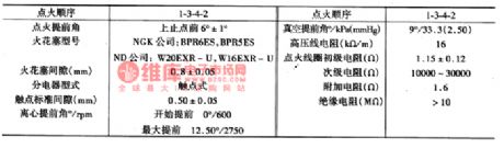
(5) the main specifications of the ignition system(as shown in figure 4)
(View)
View full Circuit Diagram | Comments | Reading(655)
556 Touching Audio Circuit
Published:2011/5/10 7:55:00 Author:Robert | Keyword: Touching, Audio
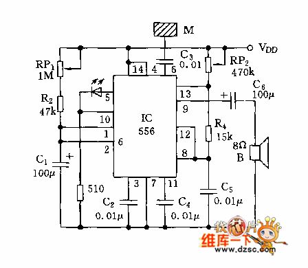
The 556 Touching Audio Circuit is shown below.
(View)
View full Circuit Diagram | Comments | Reading(794)
The Alarm Indicator Lamp and Back-up Lamp Circuit of MAZDA 929
Published:2011/5/9 23:02:00 Author:Borg | Keyword: Alarm Indicator Lamp, Back-up Lamp

View full Circuit Diagram | Comments | Reading(729)
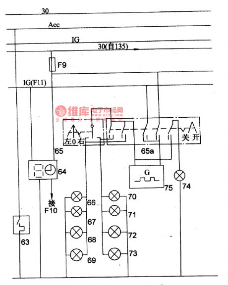
The Instrument and Alarm Lamp Circuit of MAZDA 929
Published:2011/5/9 23:07:00 Author:Borg | Keyword: Instrument, Alarm Lamp
View full Circuit Diagram | Comments | Reading(749)
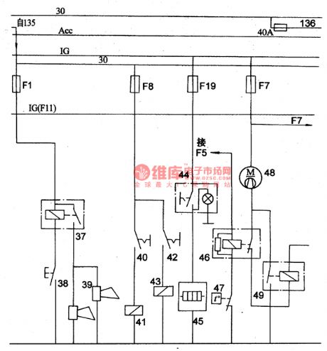
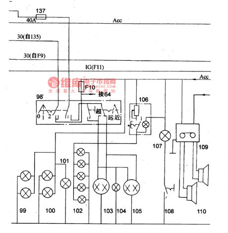
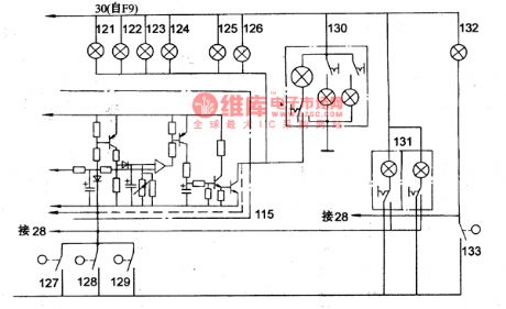
The Power Supply, Starting and Ignition Circuit of Mazda 929
Published:2011/5/9 23:39:00 Author:Borg | Keyword: Power Supply, Ignition
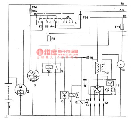
The outside size of Mazda 929 produced by Mazda Motor Corporation of Japan: 4700mm(length)*1690mm(width)*1420mm(height),4 passengers, curb weight:1160kg, total mass:1460kg.
It is equiped with a four-stage carburettor petrel engine of FE type which is installed with water-cooling single overhead camshafts, which has a spherical combustion chamber, and the diameter of its air cylinder is 86mm, piston stroke 86mm,emmission 1998ml, compression ratio∑=8.6,maximum power of the engine 72kW/5600rpm, max Nm 156N.m/3700rpm and idle speed 800~85Orpm.
1. Circuit Diagram
(View)
View full Circuit Diagram | Comments | Reading(1095)
The Brake Lamp,Speaker,Rear Defrost and Cooling Fan Principle Circuit of MAZDA 929
Published:2011/5/10 3:22:00 Author:Borg | Keyword: Brake Lamp, Loud Speaker, Rear Defrost, Cooling Fan
View full Circuit Diagram | Comments | Reading(683)
The Air-conditioning Principle Circuit of MAZDA 929
Published:2011/5/9 22:10:00 Author:Borg | Keyword: Air-conditioning, Principle Circuit, MAZDA 929
View full Circuit Diagram | Comments | Reading(759)
The Clock,Steering and Danger Sinal Circuit of MAZDA 929
Published:2011/5/9 22:00:00 Author:Borg | Keyword: Clock, Steering, Danger Sinal
The Clock,Steering and Danger Sinal Circuit of MAZDA 929 (View)
View full Circuit Diagram | Comments | Reading(647)
555 IC automatic battery charger circuit diagram(1)
Published:2011/5/9 20:38:00 Author:Ecco | Keyword: 555 , IC , automatic , battery charger
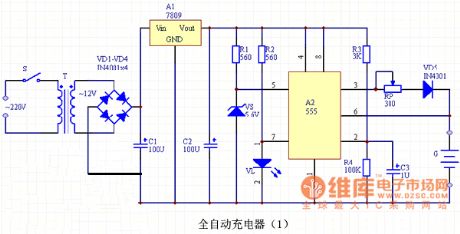
Automatic nickel-cadmium battery charger circuit is shown as the chart, the charger is mainly composed of the power supply circuit, voltage comparator and indicating circuit. The power supply is stepped-down by the T transformer, rectified by diodes VD1 ~ VD4, stabilized by three-terminal voltage regulator Manifold A1 and filtered by capacitors C1, C2, then the circuit can output stable 9V DC voltage for the charger. Voltage comparator is composed of A2 time base circuit, and it has a Zener diode VS (stable voltage 5.6V) connected to pin 5 of the control side, so the reset level of the circuit will be located in the 5.6V. VL LED is the charging indicator. A1 selects LM7809 three-terminal voltage regulator Manifold, and it should be installed aluminum heat sink. VD1 ~ VD5 use IN4001 silicon rectifier diodes. VS selects 5.6V, 1/2W Zener diode, such as UZ-5.6B, IN5232. VL uses an ordinary red LED. RP selects 2W wirewound potentiometer, R1 ~ R4 are select 1/8W carbon film resistors. C1 selects CD11-25V aluminum electrolytic capacitor, C2, C3 are the CD11-16V aluminum electrolytic capacitors. S uses an ordinary small 1 × 1 power switch. T uses 220V/12V, 5VA small, high quality power transformer.
(View)
View full Circuit Diagram | Comments | Reading(4640)
TMP87CH33N monolithic microcomputer integrated circuit diagram
Published:2011/5/9 1:08:00 Author:Ecco | Keyword: monolithic, microcomputer , integrated circuit
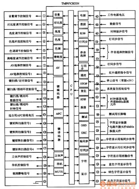
TMP87CH33N is the single-chip microcomputer integrated circuit produced by Toshiba, it is widely used in Toshiba, Konka series of movement and assembly of large-screen color TV.
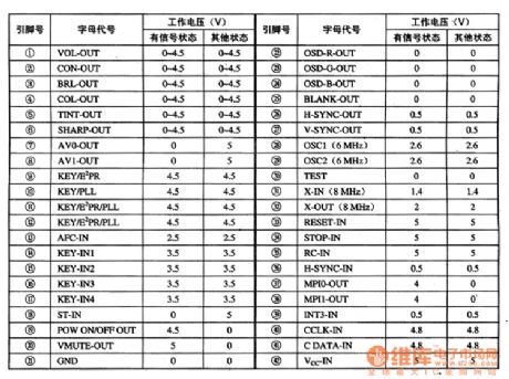
TMP87CH33N integrated circuit uses the plastic package with 42 feet in double rows, the pin functions and signal flowing are shown in Figure 1, the pin letter code and data are listed in Table 1.
(View)
View full Circuit Diagram | Comments | Reading(1542)
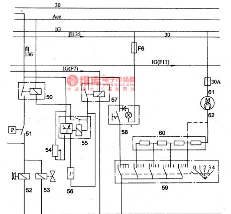
The Wiper/Washer and Power Kong Principle Circuit of MAZDA 929
Published:2011/5/9 11:15:00 Author:Borg | Keyword: Wiper/Washer, Power Kong
View full Circuit Diagram | Comments | Reading(687)
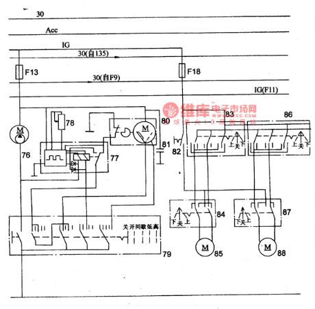
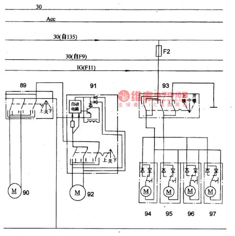
The Power Window and Control Door Lock Principle Circuit of MAZDA 929
Published:2011/5/9 11:11:00 Author:Borg | Keyword: Power Window, Control Door Lock, MAZDA 929
View full Circuit Diagram | Comments | Reading(1261)
The Lighting, Head Lamps and Radio Principle Circuit of the Mazda 929 Car
Published:2011/5/9 8:27:00 Author:Borg | Keyword: Lighting, Head Lamps, Principle Circuit
View full Circuit Diagram | Comments | Reading(722)
The Automatic Antenna,Door and Warning Lamp Circuit of the Mazda 929 Car
Published:2011/5/9 11:05:00 Author:Borg | Keyword: Automatic Antenna, Warning Lamp
View full Circuit Diagram | Comments | Reading(673)
The Interior Light,Step Lamp and Trunk Circuit of the Mazda 929 Car
Published:2011/5/9 10:59:00 Author:Borg | Keyword: Interior Light, Step Lamp, Trunk
View full Circuit Diagram | Comments | Reading(768)
The Main Technology Parameter Circuit of Mazda Battery
Published:2011/5/9 8:22:00 Author:Borg | Keyword: Technology Parameter, Battery

(2)main specifications of batteries
(View)
View full Circuit Diagram | Comments | Reading(603)
The Main Technology Parameter Circuit of the AC Motor of Mazda
Published:2011/5/9 8:19:00 Author:Borg | Keyword: Technology Parameter, AC Motor
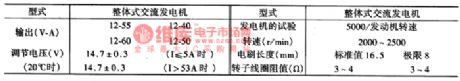
(3) main specifications of AC generators
(View)
View full Circuit Diagram | Comments | Reading(616)
The Main Technology Parameter Circuit of Mazda Motor
Published:2011/5/9 8:12:00 Author:Borg | Keyword: Technology Parameter, Mazda
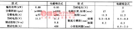
(4)main specifications of starting motors(as shown in table 3.)
(View)
View full Circuit Diagram | Comments | Reading(631)
The Bulb Power Circuit of Mazda
Published:2011/5/9 7:11:00 Author:Borg | Keyword: Bulb Power, Mazda
(6) Bulb Power(as shown in the figure)
(View)
View full Circuit Diagram | Comments | Reading(639)
| Pages:38/47 At 202122232425262728293031323334353637383940Under 20 |
Circuit Categories
power supply circuit
Amplifier Circuit
Basic Circuit
LED and Light Circuit
Sensor Circuit
Signal Processing
Electrical Equipment Circuit
Control Circuit
Remote Control Circuit
A/D-D/A Converter Circuit
Audio Circuit
Measuring and Test Circuit
Communication Circuit
Computer-Related Circuit
555 Circuit
Automotive Circuit
Repairing Circuit