
555 Circuit
Index 27
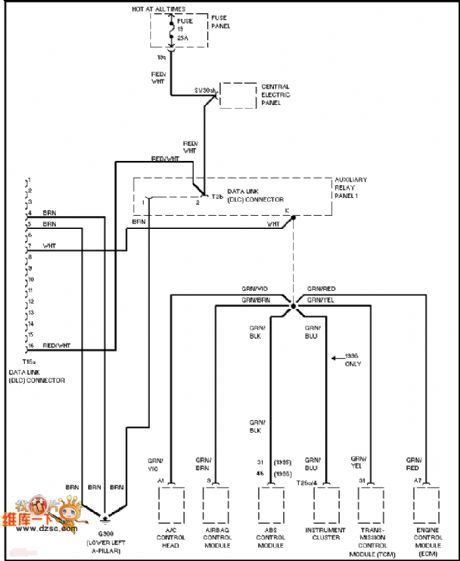
Audi computer data chart
Published:2011/6/25 10:33:00 Author:John | Keyword: computer data
View full Circuit Diagram | Comments | Reading(647)
Audi gated light circuit
Published:2011/6/25 10:20:00 Author:John | Keyword: gated light
View full Circuit Diagram | Comments | Reading(612)
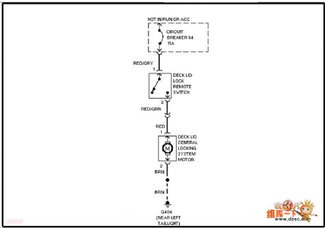
Audi active canopy opening circuit
Published:2011/6/25 6:10:00 Author:John | Keyword: active canopy
View full Circuit Diagram | Comments | Reading(633)
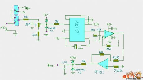
RMS voltage detection circuit
Published:2011/6/25 6:06:00 Author:John | Keyword: voltage detection
View full Circuit Diagram | Comments | Reading(1035)
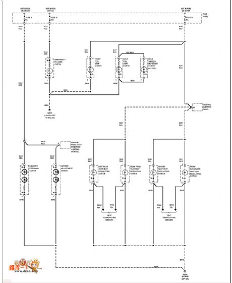
Audi (without DRL) external light circuit
Published:2011/6/25 5:52:00 Author:John | Keyword: external light
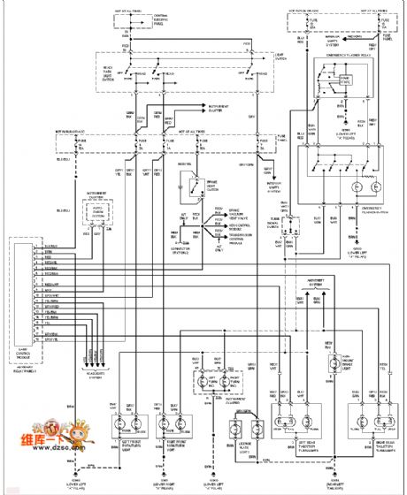
View full Circuit Diagram | Comments | Reading(685)
mixer based on LM-1496 circuit
Published:2011/6/19 7:40:00 Author:John | Keyword: mixer
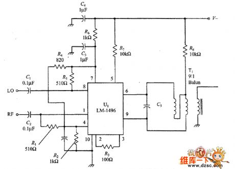
The picture shows the basic LM-1496 mixer circuit. In the figure, RF and carrier input are connected together to form a single-ended structure. Respective signals are sent from the input end through the DC blocking capacitors C1 and C2. Respective pin is connected to the ground through capacitors C3 and C4. Broadband output network includes a 9:1 RF transformer. The two outputs are combined together and their impedance is down to 50Ω. Transformer primary coil resonates the IF frequency through C5.
figure: mixer based on LM-1496 circuit (View)
View full Circuit Diagram | Comments | Reading(2123)
Double-balanced diode mixer circuit
Published:2011/6/19 7:20:00 Author:John | Keyword: diode
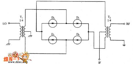
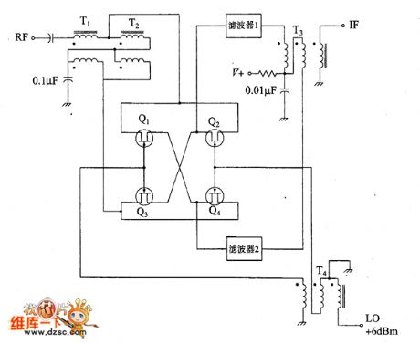
The circuit uses a ring diode mixer with balanced input, output and LO ports. It can achieve isolation between ports of 30 ~ 60dB. In the actual circuit, characteristics are also very good. Double-balanced mixer shown in the figure is widely used in a variety of designs by electronics enthusiasts and amateur radio enthusiasts. Such designs are the direct conversion receiver, single-sideband transmitter and high-performance short-wave receiver. If it is designed well, just a double-balanced mixer can work within a very wide frequency range.
(View)
View full Circuit Diagram | Comments | Reading(1042)
Duplex filter electric appliance circuit
Published:2011/6/19 7:13:00 Author:John | Keyword: Duplex filter, electric appliance
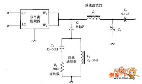
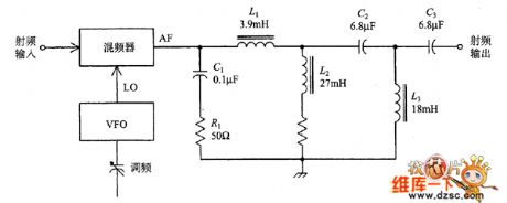
There are two tasks for duplex filter: ① to absorb unwanted mixer output signals so that they do not reflect back to the mixer; ② to send wanted signals to the output. In the figure, these two functions are achieved by two different LC networks. One is a high-pass filter and the other one is a low-pass filter. The assumption differential frequency signals in the circuit is what we need, so a high-pass filter (it’s half-power’s frequency is higher than the differential frequency) is used to guide frequency signals (that refers to the signal combination of RF and LC in the mixing process) to effective load R1. (View)
View full Circuit Diagram | Comments | Reading(814)
duplex filter for direct conversion receiver circuit
Published:2011/6/21 0:08:00 Author:John | Keyword: duplex filter, direct conversion receiver
Duplex filter for direct conversion receiver circuit is shown.
(View)
View full Circuit Diagram | Comments | Reading(931)
JFET double-balanced mixer circuit
Published:2011/6/21 0:08:00 Author:John | Keyword: double-balanced mixer
JFET double-balanced mixer circuit is shown.
(View)
View full Circuit Diagram | Comments | Reading(1486)
Eastcom EL610 cell phone failure repair circuit
Published:2011/6/21 0:09:00 Author:John | Keyword: cell phone
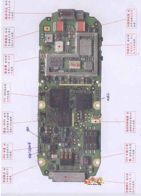
Eastcom EL610 cell phone failure repair circuit is shown.
(View)
View full Circuit Diagram | Comments | Reading(891)
NE-502 varactor tuning input circuit
Published:2011/6/19 5:09:00 Author:John | Keyword: varactor, tuning input
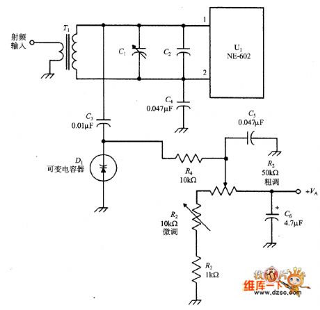
The following figure is a tuning input circuit which achieves tuning function by variable voltage capacitance diode (varactor). The total tuning capacitance in parallel consists of adjusting capacitanc C1, fixed capacitanc C2 and varactor diode’s junction capacitance D1. The total tuning capacitance is connected with transformer secondary coil L2 in order to form the resonant circuit. In order to reduce the impact of the series combination of capacitor C3/CD1, setting value of capacitor C3 is usually larger than that of the diode. In other cases, in order to make the diode capacitance become a part of resonant circuit’s capacitor, the value of capacitor C3 is very close to that of the diode. (View)
View full Circuit Diagram | Comments | Reading(1323)
Mazda 95TAURUS (3.2L, SHO) air-conditioning fan circuit
Published:2011/6/21 0:36:00 Author:John | Keyword: air-conditioning fan
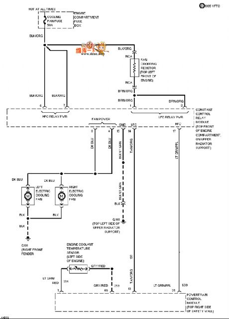
Mazda 95TAURUS (3.2L, SHO) air-conditioning fan circuit is shown.
(View)
View full Circuit Diagram | Comments | Reading(614)
Mazda 95TAURUS (3.0L, SHO) lamp monitor circuit
Published:2011/6/21 0:36:00 Author:John | Keyword: lamp monitor
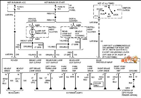
Mazda 95TAURUS (3.0L, SHO) lamp monitor circuit is shown.
(View)
View full Circuit Diagram | Comments | Reading(757)
cascode amplifier active preselector circuit
Published:2011/6/17 4:50:00 Author:John | Keyword: cascode amplifier, active preselector
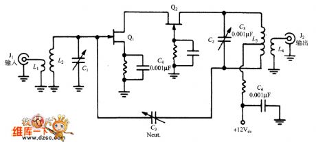
The following picture shows the circuit with a cascode VHF pre-amplifier formed by two pieces of JFET. (It means that Q1 is the direct coupling between the input common-source connection and the output gate connection Q2). In order to avoid the occurrence of self-oscillation circuit, the capacitor (NEUT) is inducted. Capacitance value is tuned to ensure that oscillation would not occur in any frequency circuit of the band-pass. In general, the circuit can be adjusted to a single channel through L2/C1 and L3/C3.
(View)
View full Circuit Diagram | Comments | Reading(1991)
azda 96TAURUS electric suspension circuit
Published:2011/6/21 0:28:00 Author:John | Keyword: electric suspension
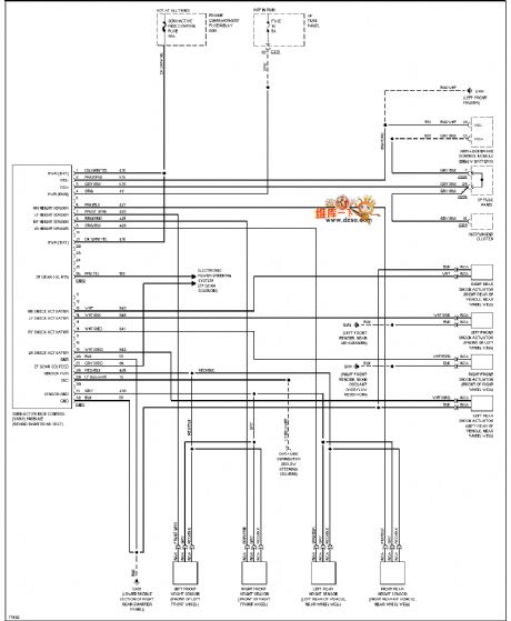
azda 96TAURUS electric suspension circuit is shown.
(View)
View full Circuit Diagram | Comments | Reading(643)
Mazda 96TAURUS lamp monitor circuit
Published:2011/6/21 0:28:00 Author:John | Keyword: lamp monitor

Mazda 96TAURUS lamp monitor circuit is shown.
(View)
View full Circuit Diagram | Comments | Reading(735)
Mazda 96TAURUS power window circuit
Published:2011/6/21 0:29:00 Author:John | Keyword: power window
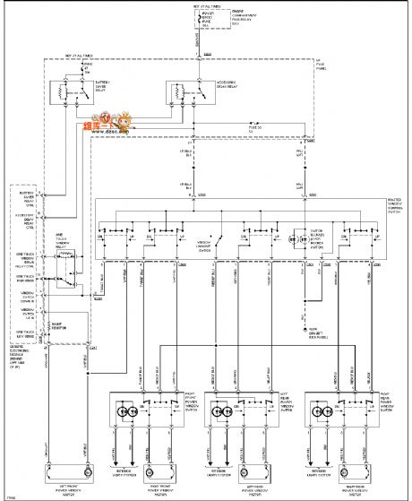
Mazda 96TAURUS power window circuit is shown.
(View)
View full Circuit Diagram | Comments | Reading(722)
Mazda 96TAURUS (3.0L) instrument panel circuit
Published:2011/6/21 0:29:00 Author:John | Keyword: instrument panel
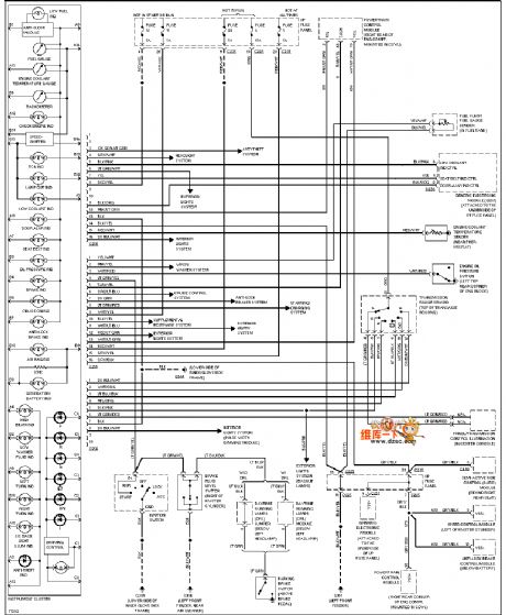
Mazda 96TAURUS (3.0L) instrument panel circuit is shown.
(View)
View full Circuit Diagram | Comments | Reading(662)
Mazda 96TAURUS (with DRL) automatic light relay circuit
Published:2011/6/21 0:29:00 Author:John | Keyword: automatic light, relay
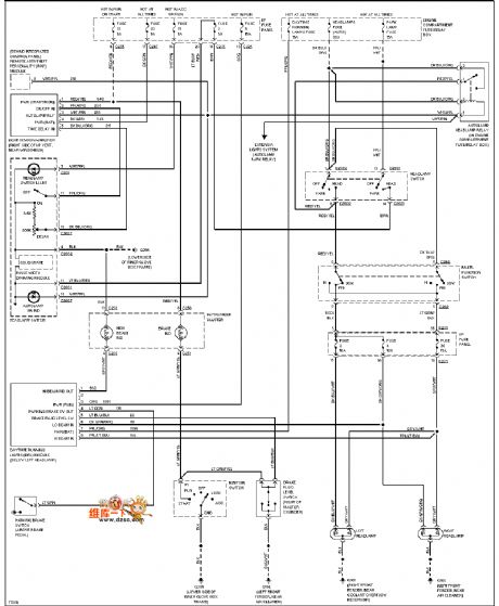
Mazda 96TAURUS (with DRL) automatic light relay circuit is shown.
(View)
View full Circuit Diagram | Comments | Reading(747)
| Pages:27/47 At 202122232425262728293031323334353637383940Under 20 |
Circuit Categories
power supply circuit
Amplifier Circuit
Basic Circuit
LED and Light Circuit
Sensor Circuit
Signal Processing
Electrical Equipment Circuit
Control Circuit
Remote Control Circuit
A/D-D/A Converter Circuit
Audio Circuit
Measuring and Test Circuit
Communication Circuit
Computer-Related Circuit
555 Circuit
Automotive Circuit
Repairing Circuit