
555 Circuit
Index 25
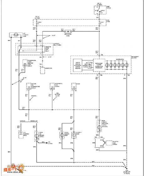
Audi instrument lighting circuit
Published:2011/6/30 10:19:00 Author:John | Keyword: instrument
View full Circuit Diagram | Comments | Reading(712)
Automatic Broadcast Controller Circuit Composed Of 555
Published:2011/6/23 8:51:00 Author:Robert | Keyword: Automatic, Broadcast, Controller
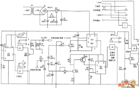
The picture shows the automatic broadcast controller circuit composed of 555. This controller is made up of buck rectifier circuit, delay circuit, relay control circuit and so on.
The F point in the picture is connected to the high-voltage indicator transformer's secondary stage's non-grounded port which is AC 6.3V. The signals of G point in the picture is from the self-monitoring signal transformer.
This controller can control the electron tube loudspeaker. It would broadcast automatically according to the operating program which is booting (warm-up 2 to 5 minutes)→openning the high-voltage (the lower limit of broadcast time)→closing high-voltage (3 seconds)→closing low-voltage. If the loudspeaker is broken, it can shut down automatically after 10 seconds. (View)
View full Circuit Diagram | Comments | Reading(770)
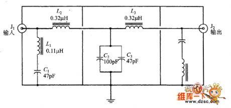
2 ~ 33MHz band-pass filter circuit formed by low-pass and high pass filter in series
Published:2011/6/20 6:31:00 Author:John | Keyword: band-pass filter, high pass filter
The filter shown in the figure is not so beautiful than the above on but with equally effectiveness. This approach is to combine the low-pass part and high pass part in series. The input section is the AM-BCB filter applied above, while the output section is the same design of a 33MHz low-pass filter. (View)
View full Circuit Diagram | Comments | Reading(836)
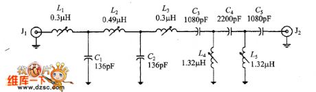
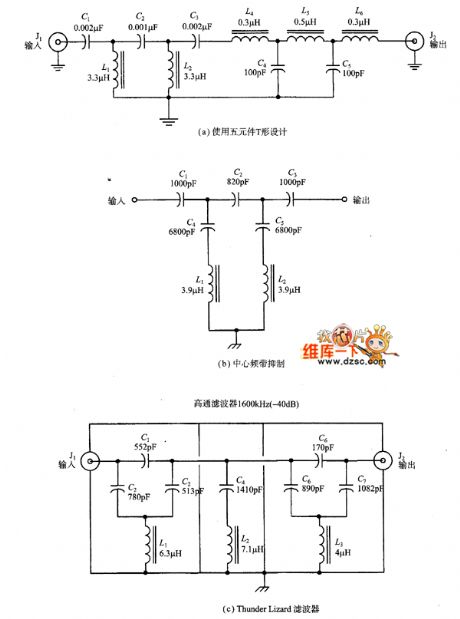
2 ~ 33MHz band-pass filter circuit
Published:2011/6/20 6:26:00 Author:John | Keyword: band-pass filter
Band-pass filter is to pass all frequencies which are higher than for those low-end cutoff frequency and are lower than the high cutoff frequency. The designed band in the shown figure is from ZMHz to 33MHz. therefore, it covers the entire HF shortwave band to eliminate interference from the LF and MWAM band and VHF television broadcasting stations. It should be noted that each part is within its own respective shield. Such is quite a good design for any multiply-section filter because it prevents the mutual influences within the components (especially the coil).
(View)
View full Circuit Diagram | Comments | Reading(1265)
Band stop filter / notch filter resonant circuit
Published:2011/6/20 6:20:00 Author:John | Keyword: Band stop filter, notch filter
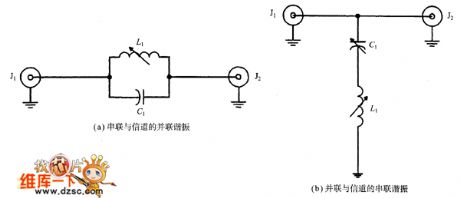
Band stop filter is a kind of band-stop filter with high Q value (referring to the narrow bandwidth). They are designed to filter out a single frequency signal. More precisely, they are to filter out a narrow-band signal around a center frequency.
Band stop filter is used to eliminate interference of a single frequency. For example, when you are close to a FM radio station, you will find that the signals cover a large area in this band or appear on a number of frequency points in this band.
(View)
View full Circuit Diagram | Comments | Reading(1928)
Qualcomm AM band suppression filter circuit
Published:2011/6/20 6:15:00 Author:John | Keyword: suppression filter, AM band
Many shortwave receivers would be adversely affected in front of the critical frequency, even if the rest parts of the receiver work well. For example, the sensitivity and intermediate frequency (IF) performance may be a good, but the third-order non-linear intercept point, dynamic range, intermediation performance are not up to the standard. If such happens, the receiver may be overloaded or without enough sensitivity or not able to obtain the desired signal. A basic source for front-end overload is the local AM band signals. Signals nearby the radio are rather strong. (View)
View full Circuit Diagram | Comments | Reading(1052)
AM BCB (500 ~ 2000kHz) band-pass filter circuit
Published:2011/6/20 6:08:00 Author:John | Keyword: band-pass filter
The picture shows the band-pass filter for AM broadcast band. This type of filter can be used for antenna and AM broadcast-band receiver’s antenna input terminal. It can reduce possible band signals which may interfere receiver or reduce the effects of the receiver. This filter is composed of a 2000kHz low-pass filter and a 500kHz high-pass filter in series.
(View)
View full Circuit Diagram | Comments | Reading(3196)
band-pass filter formed by the low-pass and high pass filters in series circuit
Published:2011/6/20 6:04:00 Author:John | Keyword: band-pass filter, high pass filter

Band-pass filter is used to allow -3dB cutoff frequency with the low end and the high end. The frequency out of this range is eliminated. A simple way to get band-pass frequency’s response is to design a band-pass filter formed by the low-pass and high pass filters in series (as shown). And the cutoff frequency of HPF is designed to be equal to the cutoff frequency on the low end of the band-pass filter. Component values are calculated by the separate parts respectively.
(View)
View full Circuit Diagram | Comments | Reading(830)
Ⅱtype low-pass filter with three component circuit
Published:2011/6/20 5:51:00 Author:John | Keyword: low-pass filter
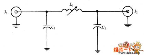
Ⅱtype low-pass filter with three component circuitis shown.
(View)
View full Circuit Diagram | Comments | Reading(770)
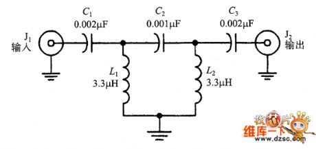
T-type low-pass filter with three component circuit
Published:2011/6/20 5:50:00 Author:John | Keyword: low-pass filter
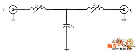
T-type low-pass filter with three component circuit is shown.
(View)
View full Circuit Diagram | Comments | Reading(1828)
NE-602 varactor tuning input circuit
Published:2011/6/21 0:12:00 Author:John | Keyword: varactor
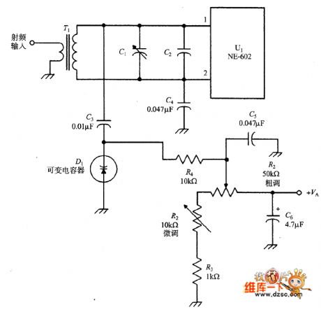
NE-602 varactor tuning input circuit is shown.
(View)
View full Circuit Diagram | Comments | Reading(921)
40W fluorescent lamp electronic ballast circuit
Published:2011/6/21 0:11:00 Author:John | Keyword: fluorescent lamp, electronic ballast
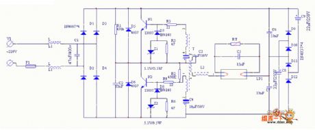
40W fluorescent lamp electronic ballast circuit is shown.
(View)
View full Circuit Diagram | Comments | Reading(19336)
Mazda 94THUNDERBIRD electric seat lumbar circuit
Published:2011/6/21 0:13:00 Author:John | Keyword: electric seat
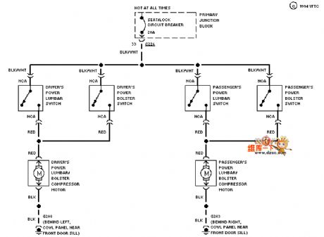
Mazda 94THUNDERBIRD electric seat lumbar circuit is shown. (View)
View full Circuit Diagram | Comments | Reading(705)
Mazda 94THUNDERBIRD (4.6L) transmission circuit
Published:2011/6/21 0:14:00 Author:John | Keyword: transmission
Mazda 94THUNDERBIRD (4.6L) transmission circuit is shown.
(View)
View full Circuit Diagram | Comments | Reading(651)
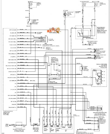
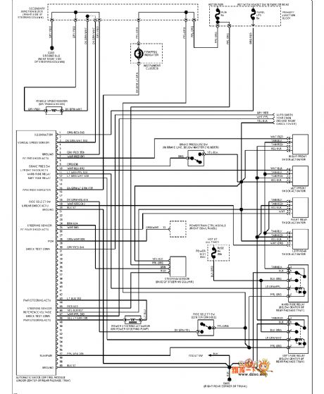
Mazda 94THUNDERBIRD (program-controlled suspension) electronic power steering circuit
Published:2011/6/21 0:14:00 Author:John | Keyword: program-controlled suspension, electronic power steering
Mazda 94THUNDERBIRD (program-controlled suspension) electronic power steering circuit is shown.
(View)
View full Circuit Diagram | Comments | Reading(1485)
Mazda 94THUNDERBIRD (without remote control door lock) inside lamp circuit
Published:2011/6/21 0:14:00 Author:John | Keyword: inside lamp, remote control door lock
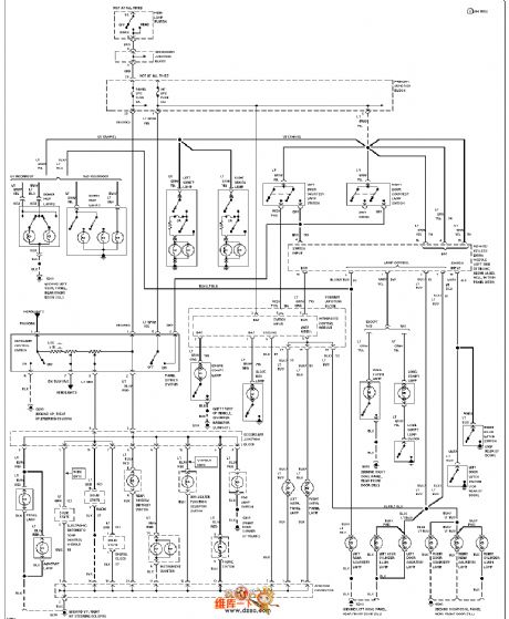
Mazda 94THUNDERBIRD (without remote control door lock) inside lamp circuit is shown.
(View)
View full Circuit Diagram | Comments | Reading(713)
Mazda 94THUNDERBIRD (with remote control door lock) inside lamp circuit
Published:2011/6/21 0:13:00 Author:John | Keyword: inside lamp, remote control door lock
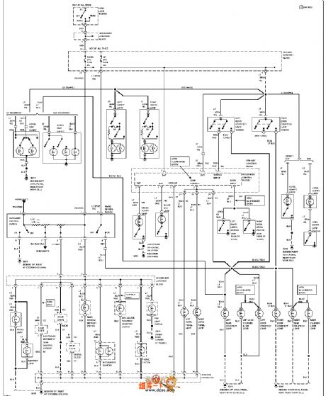
Mazda 94THUNDERBIRD (with remote control door lock) inside lamp circuit is shown.
(View)
View full Circuit Diagram | Comments | Reading(1117)
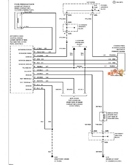
Mazda 94THUNDERBIRD electric suspension circuit
Published:2011/6/21 0:13:00 Author:John | Keyword: electric suspension
Mazda 94THUNDERBIRD electric suspension circuit is shown.
(View)
View full Circuit Diagram | Comments | Reading(627)
Mazda 94THUNDERBIRD electric door lock circuit
Published:2011/6/21 0:14:00 Author:John | Keyword: electric door lock
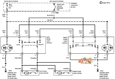
Mazda 94THUNDERBIRD electric door lock circuit is shown.
(View)
View full Circuit Diagram | Comments | Reading(1219)
Mazda 94THUNDERBIRD (3.8L, SC) starting circuit
Published:2011/6/21 0:15:00 Author:John
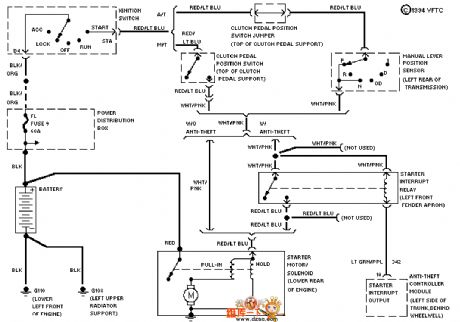
Mazda 94THUNDERBIRD (3.8L, SC) starting circuit is shown.
(View)
View full Circuit Diagram | Comments | Reading(678)
| Pages:25/47 At 202122232425262728293031323334353637383940Under 20 |
Circuit Categories
power supply circuit
Amplifier Circuit
Basic Circuit
LED and Light Circuit
Sensor Circuit
Signal Processing
Electrical Equipment Circuit
Control Circuit
Remote Control Circuit
A/D-D/A Converter Circuit
Audio Circuit
Measuring and Test Circuit
Communication Circuit
Computer-Related Circuit
555 Circuit
Automotive Circuit
Repairing Circuit