
555 Circuit
Index 23
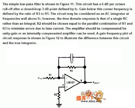
Small low-pass filter circuit
Published:2011/7/4 6:43:00 Author:John | Keyword: low-pass filter
View full Circuit Diagram | Comments | Reading(798)
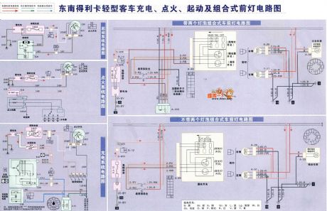
Southeast Delica minibuses charging, ignition, starting and combined headlight circuit
Published:2011/7/4 6:41:00 Author:John | Keyword: minibuses, combined headlight
View full Circuit Diagram | Comments | Reading(942)
Temperature-compensated diode input power detector circuit
Published:2011/7/4 7:03:00 Author:John | Keyword: diode, input power detector


The figure shows the Temperature-compensated diode input power detector circuit. It increases the temperature to compensate the diode VD2 and can compensate temperature to rectified voltage on the diode VD1. Diode has a negative temperature coefficient. When the temperature rises, the pressure drop of the VD1 will reduce, as well as that of VD2. It ultimately remains constant for the output voltage. Compensated Uo, PIN and the error γ of the curve are as shown. The figure also points out the error curve under the ambient temperature of +25 ℃, -40 ℃ and +85 ℃. (View)
View full Circuit Diagram | Comments | Reading(2456)
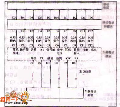
Shanghai Buick Regal phone system control circuit
Published:2011/7/4 11:02:00 Author:John | Keyword: phone system
View full Circuit Diagram | Comments | Reading(723)
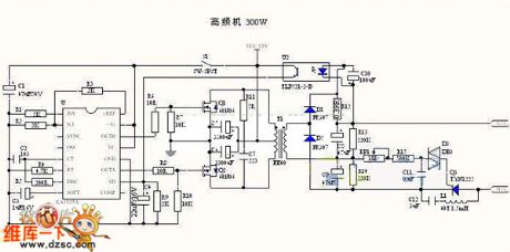
Electronic fishing device (high power) circuit
Published:2011/7/4 10:57:00 Author:John | Keyword: Electronic fishing device, fishing device
View full Circuit Diagram | Comments | Reading(4129)
Inverter circuit (150W)
Published:2011/7/4 10:55:00 Author:John | Keyword: Inverter
View full Circuit Diagram | Comments | Reading(2454)
555 adjustable speed electric toy car circuit
Published:2011/6/12 7:39:00 Author:nelly | Keyword: electric toy car
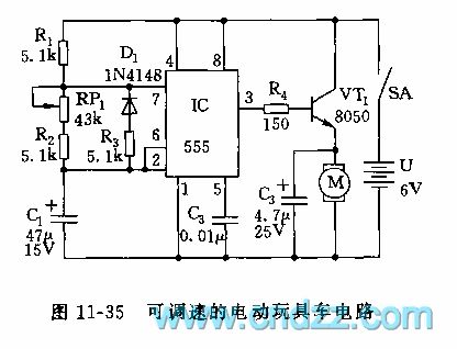
The astable multivibrator is composed of 555 and R1, R2, R3, RP1 and C1. When it is connected to power supply, because C1's voltage can not suddenly change, 555 is in set state by 2 foot's low level, VT1 is turned on by 3 foot's high level, the motor obtains electricity and runs. When C1 is charged to 2/3 VDD(4V) by R1, RP1, R2, 555 is turned and reset, 3 foot turns to low level, VT1 cuts off, the motor M is no electricity, the electric motor car slides depends on the inertial property. At this time, C1's electricity is discharged to the chip internal diacharge lamp by R3, D1, namely, the discharge circuit and charge circuit is separated due to D1's connection, and because the resistance value of RP1+R2 is larger than R3, so the discharge is done in R3.
(View)
View full Circuit Diagram | Comments | Reading(2723)
555 simplified double wires logical state judge circuit
Published:2011/6/12 9:22:00 Author:nelly | Keyword: simplified double wires, logical state
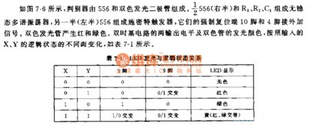
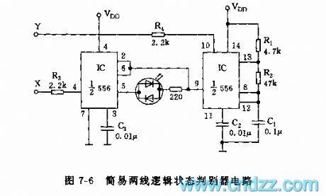
As shown on the figure 7-6, the judger consists of the 556 anddouble-color LED. The actable multivibrator consists of the the right side of 556 and R1,R2,C1. The left side of 556 makes up of the Schmitt trigger. Their 10 foot and 4 foot contact external signal. The double-color LED produces red and green light. The dual time base circuit's output level and the double color CRT's color-emitting change with the logical state of the X and Y.
(View)
View full Circuit Diagram | Comments | Reading(889)
555 ultrasonic liquid level indicator circuit
Published:2011/6/12 8:59:00 Author:nelly | Keyword: ultrasonic, liquid level
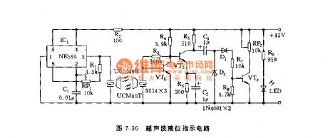
As shown on the figure 7-30, this circuit consists of the ultrasonic transmitting circuit and receiving circuit. Its hydraulic measurement is better than others, because the measured liquid's concentration and conductivity don't have effects on its ultrasonic. The ultrasonic transmitting circuitconsists of the 555,R1,RP1,C1 and ultrasonic generation. The receiving circuit consists of VT1,VT2 and detection circuit. If the liquid level is more close to the receiver sensor, the angle of the voltmeter will be bigger.
(View)
View full Circuit Diagram | Comments | Reading(1656)
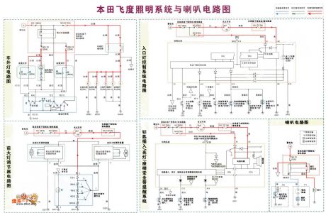
Honda Fit lighting system with speakers circuit
Published:2011/7/4 0:27:00 Author:John | Keyword: lighting system, speaker
View full Circuit Diagram | Comments | Reading(1337)
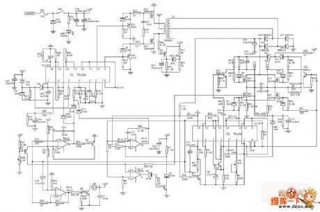
555 Closed Loop Three-phase Multi-vibrator Circuit
Published:2011/6/28 3:19:00 Author:Zoey | Keyword: 555 Closed Loop, Three-phase Multi-vibrator, Circuit
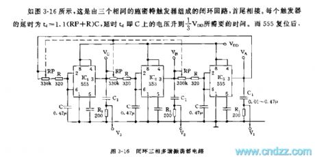
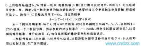
As shown in the picture 3-16, this closed loop is composed of three identical Smit triggers, end to end, the detained time of every trigger td=1.1(RP+R)C, the detained time td refers to the time needed for voltage on C ascend to 1/3 VDD. After 555 has reposited, load on C discharges to output terminal pin 3 of IC through R, W. therefore it has a same charge time constant. If the output terminals of any trigger changes, the circuit has to transmit circuit through three monostable triggers, the needed time is 3td. Output period of every IC T is 6td, the relevant frequency is
f=1/T=1/6X (RP+R) C
Value of the differential circuit R1 and C1 is selected according to the pulse width and load needed.
Three-phase signal source is widely applied in equipment like three-phase power supply, three-phase asynchronous electromotor, three-phase countercurrent, and demo teaching as well as circular lampions. (View)
View full Circuit Diagram | Comments | Reading(6599)
555 Simple Voltage-controlled Oscillator
Published:2011/6/27 4:11:00 Author:Zoey | Keyword: 555 Simple, Voltage-controlled, Oscillator

As shown in the picture 3-10, the circuit take the 555 and FET 3DJ6 as its key part to constitute a controllable multi-vibrator. As soon as terminal A and B controlled by voltage Vk, equivalent resistance between drain and source of 3DJ6 will change thereby. So, it causes the frequency change of 555.
f=1.44/(R1+2RDS)C1
This circuit can also be applied in various situations such as to transform V/F,or to identify different tones, etc. (View)
View full Circuit Diagram | Comments | Reading(1328)
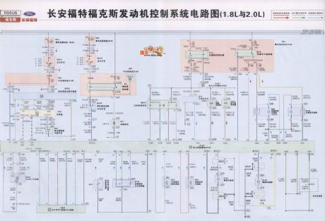
Ford Focus engine starting control system circuit
Published:2011/7/2 3:23:00 Author:John | Keyword: control system, engine
View full Circuit Diagram | Comments | Reading(1406)
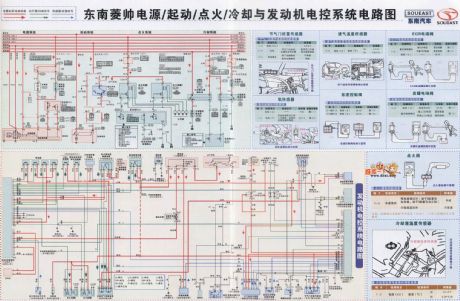
Southeast Lioncel power supply, starting, ignition, cooling system and engine control circuit
Published:2011/7/2 2:57:00 Author:John | Keyword: power supply, starting, ignition, cooling system, engine control
View full Circuit Diagram | Comments | Reading(785)
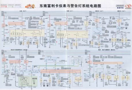
Southeast Freeca meter and warning light system circuit
Published:2011/7/2 3:21:00 Author:John | Keyword: meter, warning light system
View full Circuit Diagram | Comments | Reading(858)
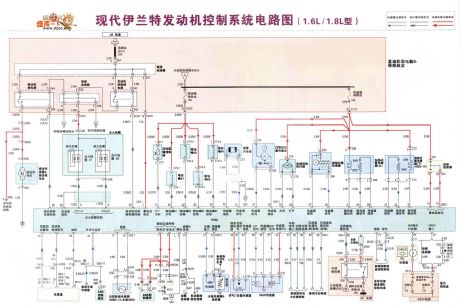
Hyundai Elantra engine control system circuit (1.6L, 1.8L model)
Published:2011/7/2 4:33:00 Author:John | Keyword: engine control system
View full Circuit Diagram | Comments | Reading(3096)
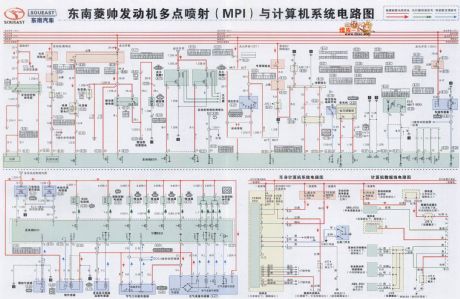
Southeast Lioncel engine multi-point injection (MPI) Y with the computer system circuit
Published:2011/7/2 2:02:00 Author:John | Keyword: computer system, engine, multi-point injection
View full Circuit Diagram | Comments | Reading(1333)
The Suzuki Antelope Century Star whole car circuit
Published:2011/6/30 22:59:00 Author:qqtang | Keyword: Suzuki, Antelope, Century Star, whole car
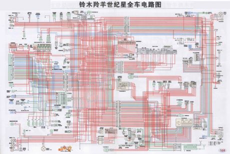
The Suzuki Antelope Century Star whole car circuit is shown as above.
(View)
View full Circuit Diagram | Comments | Reading(1106)
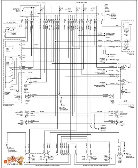
The Volkswagon external lamp circuit
Published:2011/6/30 21:19:00 Author:qqtang | Keyword: Volkswagon, external lamp
View full Circuit Diagram | Comments | Reading(699)
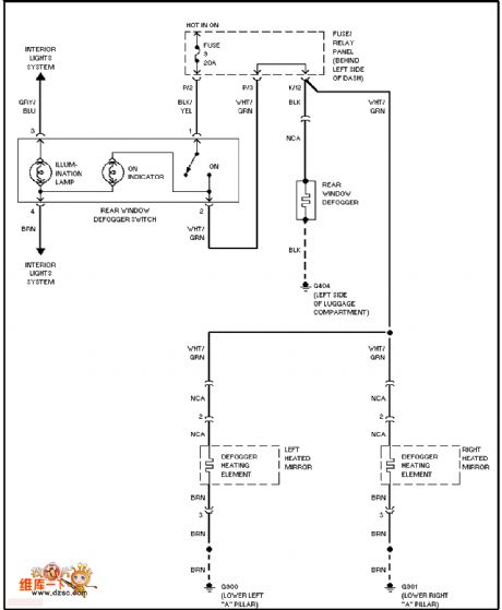
The Volkswagon demister circuit
Published:2011/6/30 21:58:00 Author:qqtang | Keyword: Volkswagon, demister
View full Circuit Diagram | Comments | Reading(729)
| Pages:23/47 At 202122232425262728293031323334353637383940Under 20 |
Circuit Categories
power supply circuit
Amplifier Circuit
Basic Circuit
LED and Light Circuit
Sensor Circuit
Signal Processing
Electrical Equipment Circuit
Control Circuit
Remote Control Circuit
A/D-D/A Converter Circuit
Audio Circuit
Measuring and Test Circuit
Communication Circuit
Computer-Related Circuit
555 Circuit
Automotive Circuit
Repairing Circuit