
Index 228
5SNS0300U120100、5SNS0225U170100、5SNS0225U172100 Internal Circuit
Published:2011/5/8 1:41:00 Author:Felicity | Keyword: Internal Circuit,
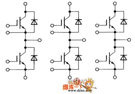
The picture above shows the 5SNS0300U120100、5SNS0225U170100、5SNS0225U172100 internal circuit. (View)
View full Circuit Diagram | Comments | Reading(483)
5SNS105V120100、5SNS0150V170100、5SNS150V172100 Internal Circuit
Published:2011/5/8 1:43:00 Author:Felicity | Keyword: Internal Circuit,
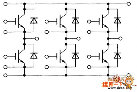
The picture above shows the 5SNS105V120100、5SNS0150V170100、5SNS150V172100 internal circuit. (View)
View full Circuit Diagram | Comments | Reading(471)
5SNR20H2500、5SNX20H2500 Internal Circuit
Published:2011/5/8 1:45:00 Author:Felicity | Keyword: Internal Circuit,
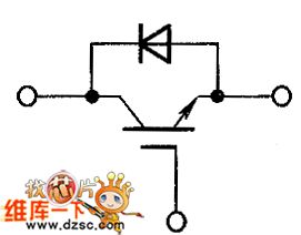
The picture above shows the 5SNR20H2500、5SNX20H2500 internal circuit. (View)
View full Circuit Diagram | Comments | Reading(762)
5SNR10H2500 Internal Circuit
Published:2011/5/8 1:47:00 Author:Felicity | Keyword: Internal Circuit,
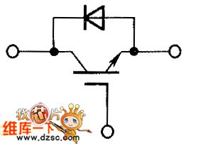
The picture above shows the 5SNR10H2500 Internal Circuit. (View)
View full Circuit Diagram | Comments | Reading(511)
5SND1200M120100 Internal Circuit
Published:2011/5/8 1:48:00 Author:Felicity | Keyword: Internal Circuit,
The picture above shows the 5SND1200M120100 internal circuit. (View)
View full Circuit Diagram | Comments | Reading(528)
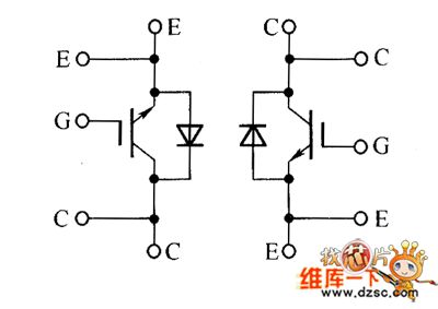
5SNA0600G650100 Internal Circuit
Published:2011/5/8 1:50:00 Author:Felicity | Keyword: Internal Circuit,
The picture above shows the 5SNA0600G650100 internal circuit. (View)
View full Circuit Diagram | Comments | Reading(528)
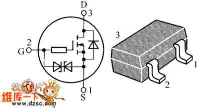
2SK3567、2SK3568、2SK3569 Internal Circuit
Published:2011/5/8 1:51:00 Author:Felicity | Keyword: Internal Circuit,

The picture above shows the 2SK3567、2SK3568、2SK3569 internal circuit. (View)
View full Circuit Diagram | Comments | Reading(823)
2SK300 Internal Circuit
Published:2011/5/8 1:53:00 Author:Felicity | Keyword: Internal Circuit,
The picture above shows the 2SK300 internal circuit. (View)
View full Circuit Diagram | Comments | Reading(599)
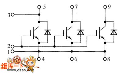
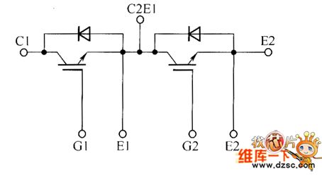
2MBI400N-060、52MBI300N-060 Internal Circuit
Published:2011/5/8 1:54:00 Author:Felicity | Keyword: Internal Circuit,
The picture above shows the 2MBI400N-060、52MBI300N-060 internal circuit. (View)
View full Circuit Diagram | Comments | Reading(533)
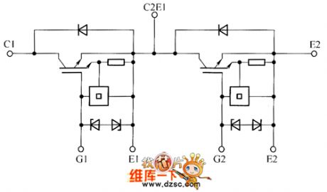
2MSI300S-120 Internal Circuit
Published:2011/5/8 1:56:00 Author:Felicity | Keyword: Internal Circuit,
2MSI300S-120 (View)
View full Circuit Diagram | Comments | Reading(525)
The Circuit of Simple Front-end Amplifier with Adjustable Gain
Published:2011/5/6 3:17:00 Author:Startrek | Keyword: Front Amplifier Circuit, Simple Power Adjustment
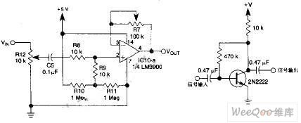
Inthis circuit, 1/4 of itcomposes a front-end amplifier with a simple power adjustment,while R7 controls the power, and if again of 10 times or more is needed, the front-end amplifier with a device parameter in the following figure can be in use.
(View)
View full Circuit Diagram | Comments | Reading(767)
Three voltage regulator series connection acquired 0-284V voltage circuit diagram
Published:2011/5/5 4:35:00 Author:Crystal Liu | Keyword: three voltage regulator series connection , acquired 0-284V voltage circuit diagram
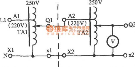
Three voltage regulator series connection acquired 0-284V voltage circuit diagram (View)
View full Circuit Diagram | Comments | Reading(486)
audiphone circuit made of discrete components
Published:2011/5/4 9:33:00 Author:TaoXi | Keyword: audiphone, discrete components
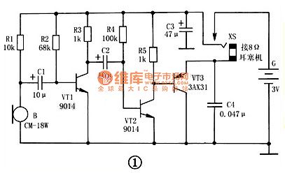
1. Principle
The audiphone circuit made of discrete components is as shown in figure 1, it is the multi-stage audio amplifier which is composed of a transistor VT1 ~ VT3. The typical RC coupled amplifier is composed of the VT1 and external RC components, this amplifier is the front audio voltage amplifier; the two-stage direct coupling type power amplifier circuit is composed of the VT2 and VT3, VT3's output impedance is low to work with the 8Ω low-impedance headphone.
2. Component selection
VT1 and VT2 select the 9014 or 3DG8 silicon NPN low power, low-noise transistor, and the current amplification coefficient is β≥100; VT3 selects the 3AX31 Ge PNP low power transistor, the current Iceo is β≥30.
B selects the CM-18W (φ10mm×6.5mm) high sensitivity electret microphone, and it has five levels of sensitivity which are indicated by the color dots: red is -66dB, light yellow is -62dB, dark yellow is -58dB, blue is -54dB, white is >-52dB. This device need to use the white dot to have high sensitivity. B can also use the electret microphone with blue dot and high sensitivity.
(View)
View full Circuit Diagram | Comments | Reading(1301)
One Kind Bridge Integrated Power Amplifier Circuit
Published:2011/5/5 20:27:00 Author:Robert | Keyword: Bridge, Integrated, Power Amplifier
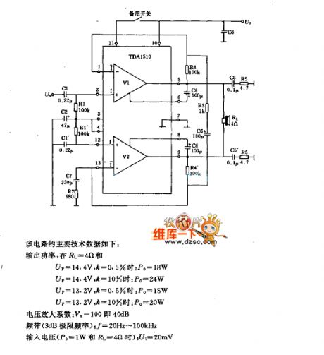
One Kind Bridge Integrated Power Amplifier Circuit is shown below.
The circuit's main technical data is listed here.
Output power, at RL=4Ω and:
when Up=14.4V andk=0.5%, Po=18W
when Up=14.4V and k=10%, Po=24W
when Up=13.2V and k=0.5%, Po=15W
when Up=13.2V and k=10%, Po=20W.
Voltage amplification factor: Va=100 which means 4dB
Bandwidth (3dB limit frequency): f=20Hz to 100KHz
Input voltage (Po=1W and RL=4Ω):Ui=20mV
(View)
View full Circuit Diagram | Comments | Reading(616)
Marantz 7 Preamplifier Circuit
Published:2011/5/5 22:09:00 Author:Robert | Keyword: Marantz 7, Preamplifier

In electron tube prestage the Marantz 7's position is paramount, and it is believed that the electron tube enthusiasts, who have never heared the name of Matantz 7,may be very few. The main circuit of Marantz 7, which is introduced in late 50 years, is shown in picture 4 below. In the circuit, V1, V2 are used as voltage amplifiers, V3 is connected as a cathode follower to be a signal buffer which acts like the NPN tube to be connected as a emitter follower. This circuit's most significant feature is its overall loop feedback design, which is a major factor making the Marantz 7 famous. But for preventing the high-frequency self-excited problem, it needs to add a 22pF capacitor between V1 and V2 to make up a high-frequency part feedback to reduce the high-frequency magnification times, and also the output port needs to connect to a tri-polar N-N type negative feedback network. This network's high-frequency high impedance is very little (about 20KΩ or less). So this design is suspected of posing a considerable burden to V3.
Although its high-frequency's open loop gain is not enough and the negative feedback's improvement for high-frequency distortion is not very well, it's strange the enthusiasts's impression to Marantz 7 is good. In this production, for V1, V2, V3 we first use the 12AX7 made in beijing, but the negative feedback network should change to be connected to the second stage which shows in the dotted portion of picture 4, and also we cancel the 22pF capacitor which used for preventing the seld-excited problem, that can effectively improve the distortion. The 12AX7 is a high U tube whose magnification is large, but its internal impedance is also large. It seems using 12AX7 for V3 is not the only best choice. We have ever used the american 5751, 12AU7 for substitution, and the high-frequency's problem has been improved in some extent, with larger dynamic range and better stability of the sound field. When using 12AU7 as the cathode output, but its distortion is less than using 12AX7 or 5751. It can use 6N10 or ECC82 instead of 12AU7. The Toshiba 5963 also has a certain quality of sound which has the same pin with 12AX7. The light filament can be supplied by 6.3V or 12.6V voltage, but in this machine we use 6.3V power supply.
The analytical ability and extension degree of high frequency and low frequency of Marantz 7 is not likely very good. These weakness can be found at some time expecially compared to the most outstanding pre-tube nowadays such as Matisse Refernce, Audio Research Referance 1, Convergent SL-1 and so on. However the most attractive things of Marantz 7 is the unspeakable beauty of the mid-frequency sound, and we think its sound has the sunshine-type bias which can express exhaustively the brightness and power of music. When playing brass music, the brightness of the instruments is full; when playing string music, the sound is also pliable and has texture, and the human voice would have more strong feelings.
We evaluate highly for this modified Marantz 7's circuit sound effect (V1, V2 use 5751, V3 use 12AU7 of Amperexr). Its sound is soft and smooth with strong texture, and its high-frequency and low frequency heavily playing performance is still be regarded as first-class, which has a certain extension degree and intensity feeling, but its mid-frequency's performance is even better. Compared to the two-stage 6SN7 negative feedback amplification circuit, the Marantz 7's circuit is better. If V1, V2 are all using Telefunken's ECC803S, V3 is using Telefunken's ECC802C too, we believe this Marantz 7 could make you do not want to use other preamplifiers.
(View)
View full Circuit Diagram | Comments | Reading(14142)
About Output 15W Integrated Power Amplifier Circuit
Published:2011/5/5 20:26:00 Author:Robert | Keyword: 15W, Integrated, Power Amplifier

About Output 15W Integrated Power Amplifier Circuit is shown below.
This circuit's main technical data is listed here.
Power Supply Us,V 20 20 20 24
Output Power Po,W(f=1kHz and k=10%) 8 9 13.5 15
Load resistance RL,Ω 8 4 2 4
(View)
View full Circuit Diagram | Comments | Reading(411)
The Discharge Circuit of a Walkie-Talkie Consisting of MOST Tubes
Published:2011/5/6 2:26:00 Author:Startrek | Keyword: Discharge Circuit, Walkie-Talkie, MOST Tubes
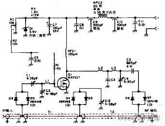
This amplifier with a power MOSFET can magnify the power of a walkie-talkie from 2W to 10W(when the wavelength is 2M). Besides, a RF(radio frequency)line switch is usedas aT/R switch.
(View)
View full Circuit Diagram | Comments | Reading(1577)
The Typical Amplifier Circuit of a Precision Instrument
Published:2011/5/6 2:07:00 Author:Startrek | Keyword: Amplifier Circuit, Precision Instrument
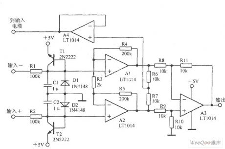
The Typical Amplifier Circuit of a Precision Instrument (View)
View full Circuit Diagram | Comments | Reading(776)
The Amplifier Circuit of Low Capacitance with High Resistance
Published:2011/5/6 1:47:00 Author:Startrek | Keyword: Amplifier Circuit, Low Capacitance, High Resistance
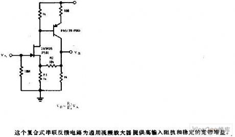
This multiple series feedback circuit can provide high-input impedance and stable wideband gain for general video amplifiers. (View)
View full Circuit Diagram | Comments | Reading(695)
Impedance Bridge Amplifier Circuit
Published:2011/5/6 1:47:00 Author:Startrek | Keyword: Impedance Bridge, Amplifier Circuit
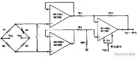
Impedance Bridge Amplifier Circuit (View)
View full Circuit Diagram | Comments | Reading(1262)
| Pages:228/250 At 20221222223224225226227228229230231232233234235236237238239240Under 20 |
Circuit Categories
power supply circuit
Amplifier Circuit
Basic Circuit
LED and Light Circuit
Sensor Circuit
Signal Processing
Electrical Equipment Circuit
Control Circuit
Remote Control Circuit
A/D-D/A Converter Circuit
Audio Circuit
Measuring and Test Circuit
Communication Circuit
Computer-Related Circuit
555 Circuit
Automotive Circuit
Repairing Circuit