
Index 227
Bootstrap composite amplification buffer (LM747,LF357) circuit
Published:2011/5/8 7:09:00 Author:TaoXi | Keyword: Bootstrap, composite amplification buffer
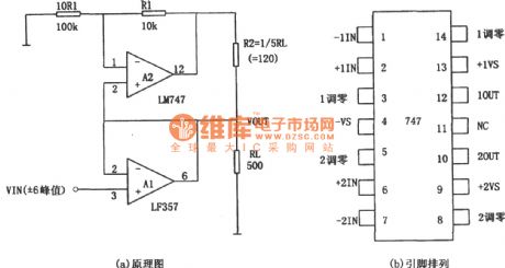
747 integrated dual op amp main parameters (typical):
(View)
View full Circuit Diagram | Comments | Reading(2973)
TA8611AN images & sound amplifier integrated circuit
Published:2011/5/8 4:14:00 Author:TaoXi | Keyword: images, sound, amplifier
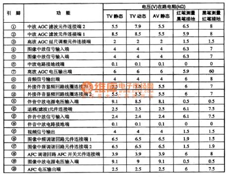
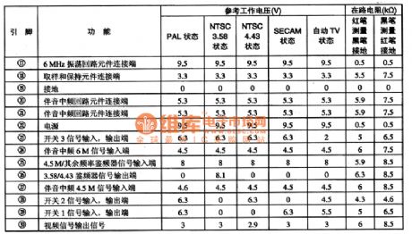
The TA8611AN images & sound amplifier integrated circuit is produced by the TOSHIBA company, this circuit can be used in imported and domestic color TVs. This IC is in the 20-pin dual in-line package, the pin functions and data is as shown in table 1.
Table 1 The pin functions and data of the TA8611AM (View)
View full Circuit Diagram | Comments | Reading(742)
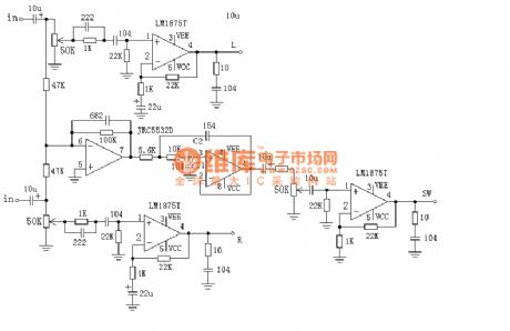
2.1 channel amplifier circuit
Published:2011/5/6 21:47:00 Author:TaoXi | Keyword: 2.1 channel, amplifier

The 2.1 channel amplifier circuit is as shown:
(View)
View full Circuit Diagram | Comments | Reading(5626)
MOSFET Amplification Circuit of Grid External Baising Circuit
Published:2011/5/7 4:03:00 Author:Joyce | Keyword: MOSFET, Amplification, Grid, External, Baising Circuit

In this amplifier circuit. the grid of MPF162 MOSFET uses an external voltage bias, so it can gain good control of the work electricity and achieve good bias conditions. (View)
View full Circuit Diagram | Comments | Reading(666)
Active amplifier circuit
Published:2011/5/8 4:04:00 Author:TaoXi | Keyword: Active, amplifier
The Active amplifier circuit is as shown:
(View)
View full Circuit Diagram | Comments | Reading(677)
TA8615N standard switching circuit
Published:2011/5/8 4:02:00 Author:TaoXi | Keyword: standard, switching

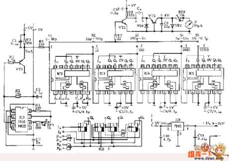
The TA8615N is designed as one kind of standard switching circuit which is produced by the TOSHIBA company, this circuit can be used in the large-screen multi-system color TVs as the multi-standard IF-sound frequency switch.
1.Features
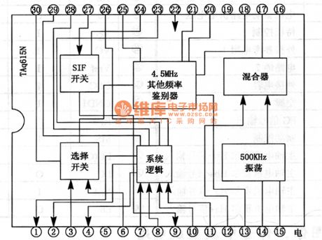
The TA8615N has the system logic circuit, the SIF electronic switch control circuit, the selector switch circuit, the mixer circuit, the 500KHz clock oscillation circuit and the 4.5MHz frequency discriminator circuit.etc. The in-circuit block diagram is as shown in figure 1.
Figure 1 The in-circuit block diagram of the TA8615N
2.Pin functions and data
The TA8615N is in the 30-pin dual in-line package, the pin functions and data is as shown in table 1.
Table 1 The pinfunctionsanddata of the TA8615N (View)
View full Circuit Diagram | Comments | Reading(1448)
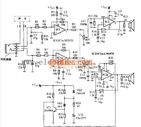
Multimedia active speaker circuit
Published:2011/5/6 7:36:00 Author:TaoXi | Keyword: Multimedia, active speaker
The Multimedia active speaker circuit is as shown:
(View)
View full Circuit Diagram | Comments | Reading(1180)
capacitance measurement circuit
Published:2011/5/8 19:55:00 Author:Christina | Keyword: capacitance, measurement
View full Circuit Diagram | Comments | Reading(748)
Transistor PK130F80 internal circuit
Published:2011/5/8 19:18:00 Author:Christina | Keyword: Transistor, internal circuit
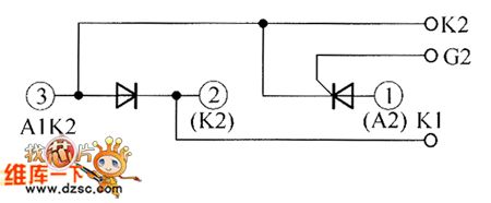
The Transistor PK130F80 internal circuit is as shown:
(View)
View full Circuit Diagram | Comments | Reading(488)
Resistance tolerance measurement circuit
Published:2011/5/8 19:35:00 Author:Christina | Keyword: Resistance tolerance, measurement
View full Circuit Diagram | Comments | Reading(613)
Logic probe circuit
Published:2011/5/8 19:34:00 Author:Christina | Keyword: Logic, probe
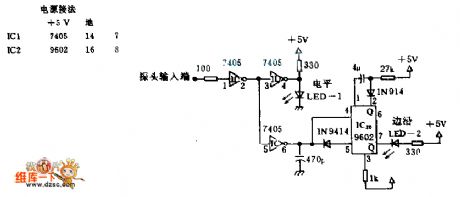
The permanently connected LED is used to indicate the TTL voltage level and the changes of this level. If the LED-1 turns on, it means the input voltage is TTL high-level voltage, If the LED-1 turns off, it means the input voltage is TTL low-level voltage. When the input voltage level changes, LED-2 lights one time. This circuit can check the voltage level, the level jump, the single pulse and the cluster pulse. Only half of each IC has used, so you need, you can use the same number of ICs as the two test probes. The in-phase driver of the monostable IC9602 is composed of the la and lc. This monostable in-phase driver IC9602 is triggered by the positive edge and negative edge of C1 and D1. If the cluster pulse's period is less than the width of the flash pulse, the edge LED-2 will always light.
(View)
View full Circuit Diagram | Comments | Reading(5)
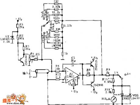
Circuit measurement circuit with the range of 100nA-1mA
Published:2011/5/8 19:15:00 Author:Christina | Keyword: Circuit measurement, 100nA-1mA
View full Circuit Diagram | Comments | Reading(506)
2.1 channel active speaker circuit
Published:2011/5/6 21:48:00 Author:TaoXi | Keyword: 2.1 channel, active speaker
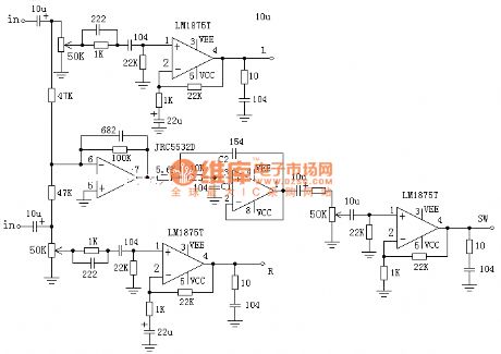
The 2.1 channel active speaker circuit is as shown:
(View)
View full Circuit Diagram | Comments | Reading(2729)
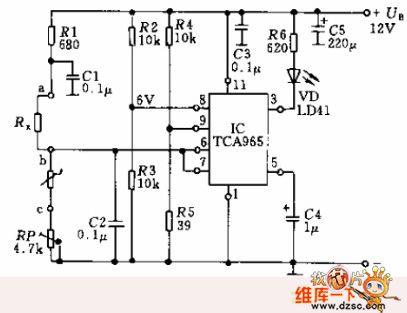
The Static Offset Circuit of the Triode Common-Emitter Amplifier
Published:2011/5/6 20:44:00 Author:Borg | Keyword: Static offset, Common-Emitter Amplifier
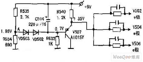
In the following figure, there is a circuit formed by static potentials and bias voltages of common-emitters(i.e V502,V504 and V506). When the supply voltage changes even a little, the static operating point will be effected, and the brightness on the screen will be effected because the static electrode potential of the output tube changes. Therefore, with this circuit, the bias voltage on the emitter of the amplifier changes synchronously with the supply power of +9V, i.e even when this supply power changes a little, the voltages on the emitters, V502,V504 and V506, will change subsequently, making sure that both of the common- and grounded- transistors won’t change because of the supply power, which means that the static potentials of V501,V503 AND V506 keep steady. This character can not only keep the consistence of piles of products, but also make the brightness of a singal screen not to be effected by the little changes of the supply power.
(View)
View full Circuit Diagram | Comments | Reading(633)
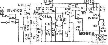
The Amplifier Circuit of Dually Amplified TV Antennas
Published:2011/5/6 20:50:00 Author:Borg | Keyword: Amplifier Circuit, Dually Amplified TV Antennas
The Amplifier Circuit of Dually Amplified TV Antennas (View)
View full Circuit Diagram | Comments | Reading(2191)
AOP609 Internal Circuit
Published:2011/5/8 1:34:00 Author:Felicity | Keyword: Internal Circuit,
The picture above shows the AOP609 internal circuit. (View)
View full Circuit Diagram | Comments | Reading(542)
AOL1401 Internal Circuit
Published:2011/5/8 1:35:00 Author:Felicity | Keyword: Internal Circuit,
The picture above shows the AOL1401 internal circuit. (View)
View full Circuit Diagram | Comments | Reading(488)
AOD434 Internal Circuit
Published:2011/5/8 1:37:00 Author:Felicity | Keyword: Internal Circuit,
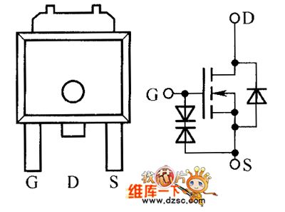
The picture above shows the AOD434 internal circuit. (View)
View full Circuit Diagram | Comments | Reading(515)
5SNX13H2500 Internal Circuit
Published:2011/5/8 1:38:00 Author:Felicity | Keyword: Internal Circuit,
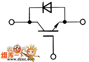
The picture above shows the 5SNX13H2500 intenal circuit. (View)
View full Circuit Diagram | Comments | Reading(480)
5SNX10H2500 Internal Circuit
Published:2011/5/8 1:40:00 Author:Felicity | Keyword: Internal Circuit,
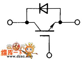
The picture above shows the 5SNX10H2500 internal circuit. (View)
View full Circuit Diagram | Comments | Reading(526)
| Pages:227/250 At 20221222223224225226227228229230231232233234235236237238239240Under 20 |
Circuit Categories
power supply circuit
Amplifier Circuit
Basic Circuit
LED and Light Circuit
Sensor Circuit
Signal Processing
Electrical Equipment Circuit
Control Circuit
Remote Control Circuit
A/D-D/A Converter Circuit
Audio Circuit
Measuring and Test Circuit
Communication Circuit
Computer-Related Circuit
555 Circuit
Automotive Circuit
Repairing Circuit