
Index 225
Integrated inside circuit box circuit
Published:2011/5/9 5:06:00 Author:John | Keyword: Integrated circuit, inside circuit box
(View)
View full Circuit Diagram | Comments | Reading(588)
-55℃ to +150℃ digital thermometer circuit
Published:2011/5/10 22:31:00 Author:Christina | Keyword: digital, thermometer circuit
This circuit is composed of the new semiconductor temperature sensor IC two-terminal device SL590 and the 3-bit half-digital voltage panel meters 5GM14433, and it can measure the -55 to +150 ℃ temperature range. The temperature is changed into the current signal by SL590, and the current signal is changed into the voltage signal (corresponds to the Celsius temperature) by the operational amplifier, then the voltage signal gets into the 5GM14433's VX input port and becomes the digital signal that is desplayed by the LED.
The power supply is the AC, DC-style. AC power supply has 220V voltage, or you can use four 1.5V batteries as the power.
(View)
View full Circuit Diagram | Comments | Reading(480)
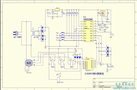
Digital long time delay circuit
Published:2011/5/10 22:31:00 Author:Christina | Keyword: Digital, long time delay
General long delay circuit usually needs the electrolytic capacitors or high impedance circuits. Theses delay circuit has the poor stability and low delay accuracy.
Here is one kind of digital long time delay circuit, it completely abandons the large electrolytic capacitors and high impedance circuits, and it has high delay accuracy.
The core component of this circuit is the MC14521B, it is a 24-stage frequency circuit and has the inverter. If you connect the trigger input port to the ground or do not add any signals, the circuit will get into the delay state, the delay time is controlled by the range switch X and the 100KΩ potentiometer.
If we connect X with point A, the delay time is 1 minute 40 seconds to 18 minutes and 30 seconds. The delay time is adjusted by the 100KΩ potentiometer. If you need the longer delay time, you can use the large capacitor instead of the 39nF capacitor. At this time, the delay time will be more than one week.
With the reliable and stable delay, we suggest you to use the 6 to 15V power supply. The prototype's voltage is 12V. (View)
View full Circuit Diagram | Comments | Reading(1450)
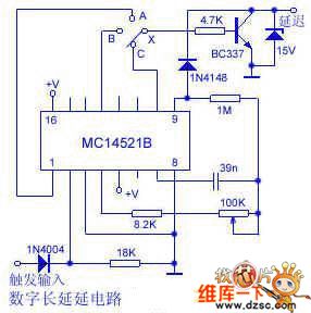
Crystal Oscillator Principle Circuit
Published:2011/5/10 3:56:00 Author:Sharon | Keyword: Crystal Oscillator
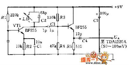
Figure shows a simple oscillator which can be used in receiver. Output Oscillation signal can be connected to operational amplifier TDA1220A pin 1 (the amplitude of the output voltage UA is about 50 ~ 100mV). (View)
View full Circuit Diagram | Comments | Reading(1451)
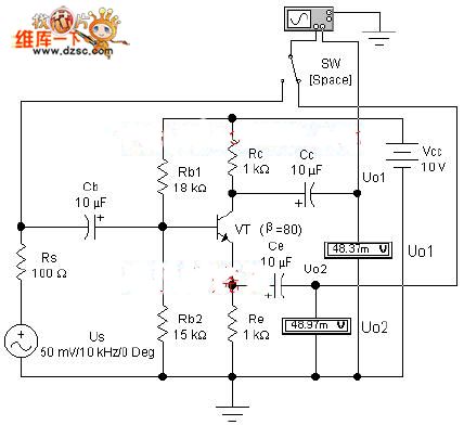
Pressure-separation Negative Feedback Bias Current Amplifying Experiment Circuit
Published:2011/5/10 3:42:00 Author:Sharon | Keyword: Pressure-separation, Negative Feedback, Bias, Amplifying
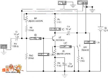

First, demonstration contents1. The composition of amplifier circuit and functions of its components. 2. Quiescent point set, and demonstration of waveform distortion. 3. Dynamic analysis of amplifying circuit.
Second,demonstrative circuit
Figure 1 Pressure-separation negative feedback bias current amplifying experiment circuit
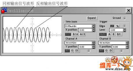
Third, features demonstration
Figure 2 Applying oscilloscope display box showing the input and output signal waveform and phase relationship (View)
View full Circuit Diagram | Comments | Reading(636)
Phase wave-detector circuit
Published:2011/5/10 22:32:00 Author:Christina | Keyword: Phase, wave-detector
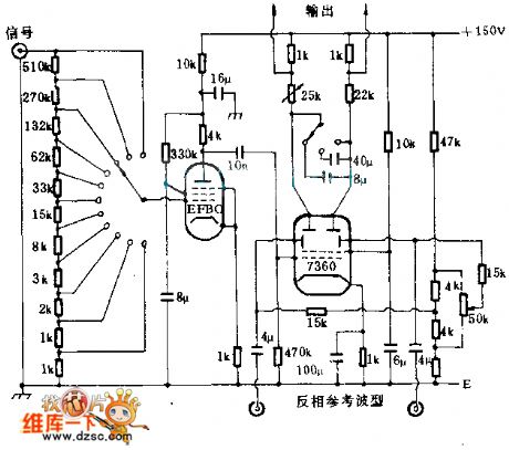
The IR system balance full-wave phase wave-detector is as shown, the RCA7360 is the beam deflection tube, this deflection tube has two deflectors to switch the electron beam from one electrode to another electrode. The conversion function of the deflector is controlled by the reference waveform which is synchronous with the into signal. If you connect a capacitor (8μF or 40μF) to the output port, and charge it with two half-cycle, you can get the doubling of the input value's standard.
(View)
View full Circuit Diagram | Comments | Reading(741)
Phase Amplifier Analysis Experiment Circuit
Published:2011/5/10 3:46:00 Author:Sharon | Keyword: Phase Amplifier
First, demonstrationContent 1. The composition of phase circuit and static analysis. 2. Dynamic analysis of phase circuit.
Figure 1 Phase amplifier analysis experiment circuit
Second, demonstrative circuit
3. features demonstration
(View)
View full Circuit Diagram | Comments | Reading(570)
NTLTD7900ZR2 Internal Circuit
Published:2011/5/10 2:33:00 Author:Sharon | Keyword: Internal
NTLTD7900ZR2'sInternal Circuit is shown below:
(View)
View full Circuit Diagram | Comments | Reading(497)
Op-amp device logarithmic tables circuit
Published:2011/5/10 22:30:00 Author:Christina | Keyword: Op-amp, logarithmic tables
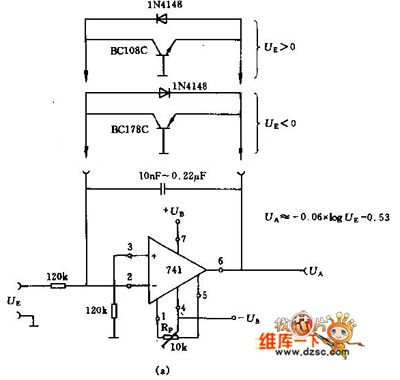
The op-amp device logarithmic tables circuit is as shown:
Figure (a) circuit: you can choose the NPN or PNP transistor according to the input signal's polarity, the voltage can be adjusted by the adjusting potentiometer RP.
Figure (b) circuit can be used as the anti-tachometer, also you can choose the NPN or PNP transistor according to the input signal's polarity. (View)
View full Circuit Diagram | Comments | Reading(1406)
The Encoding Intergrated Circuit of the BT864 Digital Video
Published:2011/5/10 22:06:00 Author:Borg | Keyword: Encoding Intergrated Circuit, Digital Video
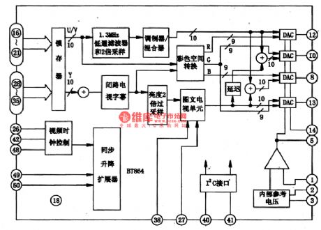

BT864 is a intergrated circuit of digital video encoding specially designed for video systems, which is widely used in many kinds of VCD and DVD players.
1.Function Features
The BT864 intergrated circuits support NTSC-M(China, Japan),PLB、D、G、H、I(Europe, Asia),PLA-M、PAL-N、PAL-NC. It has sub-circuits of the latche, brightness processing unit,color processing unit, CCTV subtitle processing unit,teletext unit,DAC and 12C interface,etc, whose internal circuit if chips are shown in Figure 1.
Figure 1 the internal circuit of BT864 chips
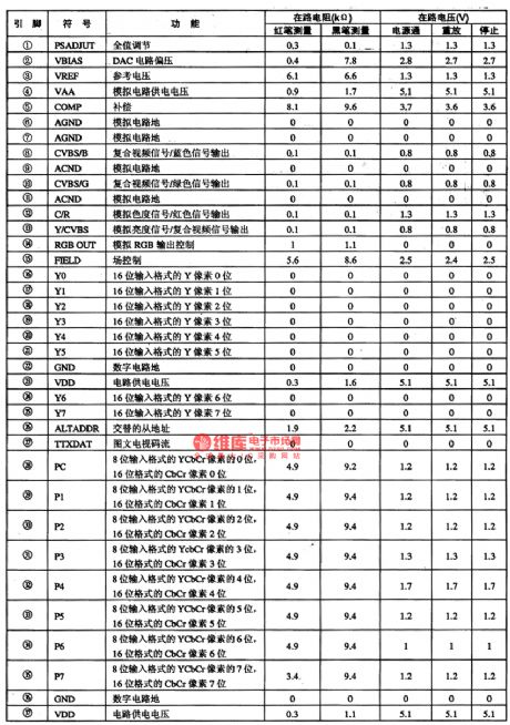
2.pin functions and relevent data
BT864 intergrated circuits are pinned with 52 pinnings, whose pin functions and data are listed in Table 1.
Table 1. pin functions and relevent data of the BT864 intergrated circuit (View)
View full Circuit Diagram | Comments | Reading(661)
Thermocouple amplifier (ISO122P/124, INA101) circuit diagram
Published:2011/5/10 21:45:00 Author:Ecco | Keyword: Thermocouple , amplifier
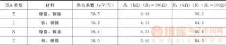
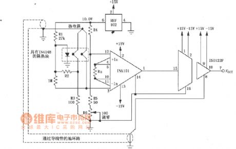
The thermocouple amplifier circuit composed of ISO122P/I24 and INA101 instrumentation amplifier, REF102 voltage reference is shown as the chart, it has the features of loop elimination, cold junction compensation and the high scale turning off end. Thermocouple can test temperature in the field, the temperature signal is converted to voltage signal and amplified by instrumentation amplifier INA101 and sent to ISO122P/124, and it is isolated amplified output by the ISO122P/124. The resistor RG is used to set the INA101 gain. The circuit is characterized by a thermocouple connecting to the ground of ISO122P/124 secondary side, that is the formation of the same potential, thereby it eliminates the interference caused by ground loops. Diode 1N4148 is the cold junction compensation of the thermocouple, 1MΩ resistor constitutes the high-end off circuit. The type and parameters of ISA are listed in the table below.
(View)
View full Circuit Diagram | Comments | Reading(2534)
Ring wave detector circuit
Published:2011/5/9 10:06:00 Author:Christina | Keyword: Ring wave, detector
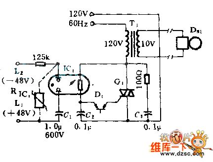
The optical isolator with the neon light and photosensitive resistance can be used as the interface between the telephone line and the ring. The neon light will turn on if there is the 100Vac ring signal, at the same time C1 is isolated to keep the battery voltage range. If we use the varistor RLC1, the rated voltage of the capacitor can be reduced to 400V. The SCR switch Q1 and the line transformer primary series connection supply the 20HZ ringing frequency synchronization for the phone system.
(View)
View full Circuit Diagram | Comments | Reading(595)
The Circuit of Capacitors being used as Transformers
Published:2011/5/8 9:18:00 Author:Crystal Liu | Keyword: Capacitors, transformer
The Circuit of Capacitors being used as Transformers
(View)
View full Circuit Diagram | Comments | Reading(446)
The Intergrated Circuit Driven by the BA6849 Three-phase Spindle Motor
Published:2011/5/9 22:52:00 Author:Borg | Keyword: Intergrated Circuit, Three-phase
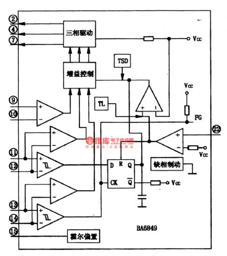
BA6849 is a intergrated circuit diven by the BA6849 three-phase spindle motor, which can translate the defult control signal of the spindle into three-phase drive voltage and therefore drives the three-phase spindle motor. This circuit is used in the cores of DVD players.
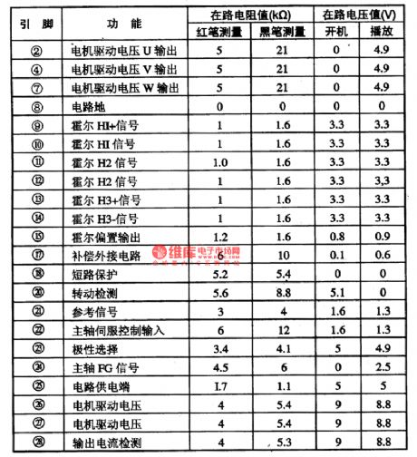
As shown in figure 1 is the internal circuit of BA6849 chips, it is pinned in flat type 28 with cooling ribs, the pin functions and data are listed in figure 1 in which the pinnings ①、③、⑤、⑥、(16)、(19) are listed at the foot of the page.
Figure 1. the internal circuit of the BA6849 chip
Table 2. the pin functions and data of the BA6849 chip (View)
View full Circuit Diagram | Comments | Reading(777)
Programmable instrument amplifier circuit diagram based on a gain
Published:2011/5/10 3:23:00 Author:Nicole | Keyword: Programmable instrument, amplifier, gain
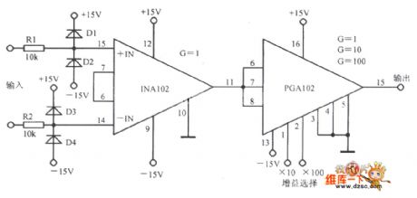
View full Circuit Diagram | Comments | Reading(540)
Direct optical coupling isolating amplifier circuit diagram
Published:2011/5/10 3:05:00 Author:Ecco | Keyword: Direct , optical coupling , isolating , amplifier
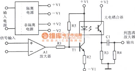
View full Circuit Diagram | Comments | Reading(670)
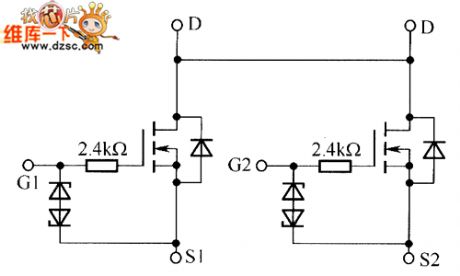
QS5U16, QS5U17 Internal Circuit
Published:2011/5/9 4:08:00 Author:Sharon | Keyword: Internal
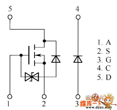
QS5U16, QS5U17 Internal Circuit is shown in below figure:
(View)
View full Circuit Diagram | Comments | Reading(585)
Electric Motor Triangle Voltage Reducing Start Circuit
Published:2011/5/6 11:15:00 Author:Joyce | Keyword: Electric Motor, Triangle, Voltage Reducing, Start
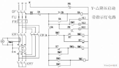
View full Circuit Diagram | Comments | Reading(634)
Monostable Trigger Circuit Composed of 555
Published:2011/5/9 5:11:00 Author:Sue | Keyword: Monostable, Trigger
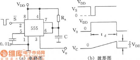
As seen in the figure is the monostable trigger circuit composed of 555. The function terminals in the figure are corresponding to this. We can see that the monostable circuit is made only by connecting a timing network composed of resistance Ra and capacity C. (a) Circuit (b) Waveform. (View)
View full Circuit Diagram | Comments | Reading(574)
Using NE555 Skillfully as Audio Power Amplifier Circuit 1
Published:2011/5/7 6:27:00 Author:Joyce | Keyword: Using NE555 Skillfully as, Audio Power, Amplifier
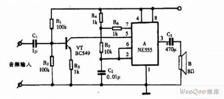
Using NE555 Skillfully as Audio Power Amplifier Circuit (View)
View full Circuit Diagram | Comments | Reading(2447)
| Pages:225/250 At 20221222223224225226227228229230231232233234235236237238239240Under 20 |
Circuit Categories
power supply circuit
Amplifier Circuit
Basic Circuit
LED and Light Circuit
Sensor Circuit
Signal Processing
Electrical Equipment Circuit
Control Circuit
Remote Control Circuit
A/D-D/A Converter Circuit
Audio Circuit
Measuring and Test Circuit
Communication Circuit
Computer-Related Circuit
555 Circuit
Automotive Circuit
Repairing Circuit