
Index 237
Nanosecond pulse detection circuit
Published:2011/4/26 18:42:00 Author:Christina | Keyword: Nanosecond pulse, detection
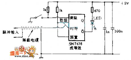
This circuit can detects the no-reproduce digital pulse of microsecond or nanosecond. The bistable IC sends the pulse information from the data input port to the Q output port, and this bistable IC uses the clock pulse along as the time base to stimulate the LED indicator.
(View)
View full Circuit Diagram | Comments | Reading(967)
Inductive headset circuit
Published:2011/4/26 9:13:00 Author:TaoXi | Keyword: Inductive headset
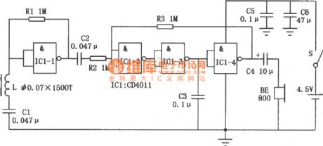
The inductive headset can be used in electronic teaching, home television and stereo audio signal wireless reception applications, this device eliminates the inconvenience of headphone cable, and avoid to interfere other people's rest and study. This circuit is composed of the four NAND gate integrated circuit CD4011 and some external components, the circuit is simple and has excellent sound quality, it is easy to make. (View)
View full Circuit Diagram | Comments | Reading(958)
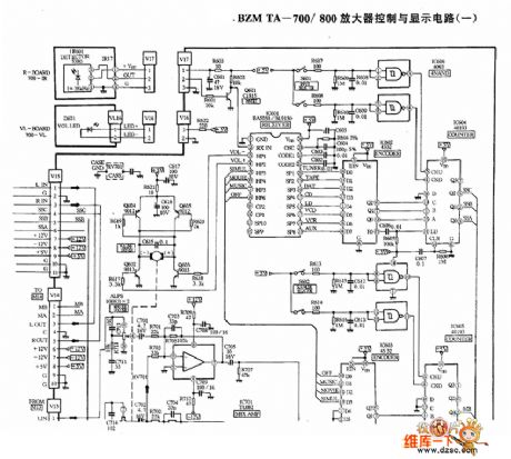
BZMTA-700/800 amplifier control and display circuit diagram
Published:2011/4/26 10:31:00 Author:Nancy | Keyword: amplifier, control and display
(View)
View full Circuit Diagram | Comments | Reading(524)
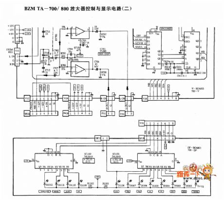
BZMTA-700/800 amplifier control and display circuit diagram (-)
Published:2011/4/26 10:38:00 Author:Nancy | Keyword: amplifier, control and display
(View)
View full Circuit Diagram | Comments | Reading(510)
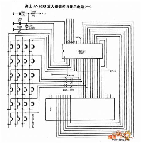
Gaoshi AV9095 amplifier key and display circuit diagram
Published:2011/4/26 10:47:00 Author:Nancy | Keyword: Gaoshi, amplifier, key and display
(View)
View full Circuit Diagram | Comments | Reading(699)
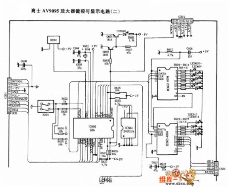
Gaoshi AV9095 amplifier key and display circuit diagram (-)
Published:2011/4/26 10:46:00 Author:Nancy | Keyword: Gaoshi, amplifier, key and display
(View)
View full Circuit Diagram | Comments | Reading(653)
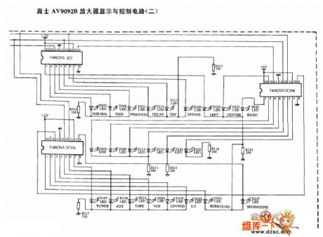
Gaoshi AV9092B amplifier display and control circuit diagram
Published:2011/4/26 10:50:00 Author:Nancy | Keyword: Gaoshi, amplifier, display and control
(View)
View full Circuit Diagram | Comments | Reading(439)
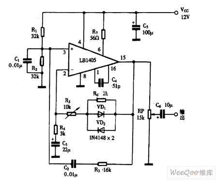
Using LB1405 as pre-amplifier circuit diagram
Published:2011/4/26 3:17:00 Author:Rebekka | Keyword: pre-amplifier circuit
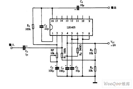
Using LB1405 as pre-amplifier circuit diagram is shown as above. (View)
View full Circuit Diagram | Comments | Reading(4873)
Using LB1405 as the audio signal amplifier circuit diagram
Published:2011/4/26 3:16:00 Author:Rebekka | Keyword: audio signal amplifier
Using LB1405 as the audio signal amplifier circuit diagram is shown as above. (View)
View full Circuit Diagram | Comments | Reading(2189)
Using LM386 as BTL amplifier circuit diagram
Published:2011/4/26 3:11:00 Author:Rebekka | Keyword: amplifier circuit
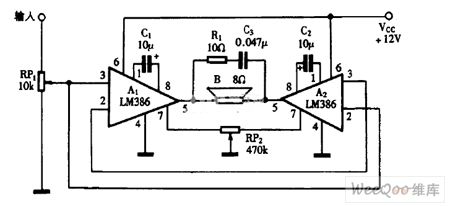
Using LM386 as BTL amplifier circuit diagram is shown as above. (View)
View full Circuit Diagram | Comments | Reading(10740)
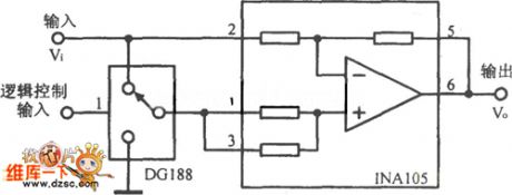
Pulse amplifier circuit
Published:2011/4/25 20:32:00 Author:Nicole | Keyword: Pulse amplifier
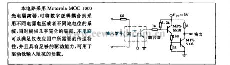
This circuit adopts Motorola MOC1000 photoelectric isolator, it can couple digital logic to the adopted different power supply or level system, they provide almost complete isolation. The circuit can satisfy the need of transfer characteristicin the instrument application, it has enough drive capability, it can be used to drive the low input resistance load. (View)
View full Circuit Diagram | Comments | Reading(966)
400Hz Sine Wave Circuit Using Light-Emitting Diode And Operational Amplifier
Published:2011/4/25 7:27:00 Author:Robert | Keyword: Light-Emitting Diode, Operational Amplifier, 400Hz, Sine Wave
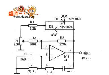
400Hz Sine Wave Circuit Using Light-Emitting Diode And Operational Amplifier is shown below:
(View)
View full Circuit Diagram | Comments | Reading(1040)
Practical Numerical Control Or Inverter Circuit
Published:2011/4/25 7:25:00 Author:Robert | Keyword: Numerical Control, Inverter
Practical Numerical Control Or Inverter Circuit is shown below:
(View)
View full Circuit Diagram | Comments | Reading(435)
75Ω Impedance Linear Amplification Circuit Consists Of RF2320
Published:2011/4/24 6:02:00 Author:Robert | Keyword: 75Ω, Impedance Linear Amplification

75Ω Impedance Linear Amplification Circuit Consists Of RF2320 is shown below. J1 and J2are 75Ω Connectors.
(View)
View full Circuit Diagram | Comments | Reading(591)
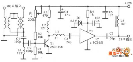
Ordinary VHF antenna amplifier circuit principle diagram
Published:2011/4/25 5:08:00 Author:May | Keyword: Ordinary VHF, antenna amplifier
View full Circuit Diagram | Comments | Reading(1268)
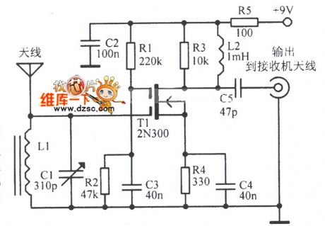
Full Channel TV antenna amplification circuit
Published:2011/4/25 5:07:00 Author:May | Keyword: Full Channel, TV antenna amplification
View full Circuit Diagram | Comments | Reading(1684)
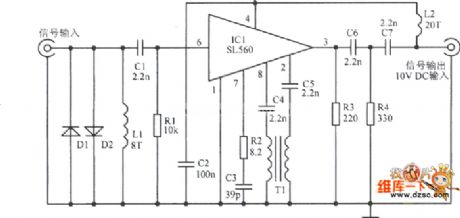
Simple shortwave signal amplifier circuit diagram
Published:2011/4/25 5:19:00 Author:May | Keyword: Simple, shortwave signal, amplifier
View full Circuit Diagram | Comments | Reading(1328)
Composed of MOSFETT symmetrical power amplifier circuit diagram
Published:2011/4/25 2:24:00 Author:Rebekka | Keyword: MOSFETT, symmetrical power amplifier

Figure 1 is symmetrical power amplifier circuit constituted by the MOSFETT. The circuit uses a single-ended input mode push-pull output Class A, the output power is lOW. (View)
View full Circuit Diagram | Comments | Reading(4473)
Low Brightness Measurement Circuit
Published:2011/4/24 19:53:00 Author:Christina | Keyword: Low Brightness, Measurement
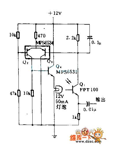
This circuit uses the light to bias the phototransistor Q1 to improve the response time, so we can get the maximum photosensitive sensitivity.
(View)
View full Circuit Diagram | Comments | Reading(459)
Flashlight Retrofitting Light Modulator Circuit
Published:2011/4/23 4:00:00 Author:Joyce | Keyword: Flashlight, Retrofitting, Light Modulator
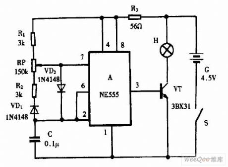
View full Circuit Diagram | Comments | Reading(606)
| Pages:237/250 At 20221222223224225226227228229230231232233234235236237238239240Under 20 |
Circuit Categories
power supply circuit
Amplifier Circuit
Basic Circuit
LED and Light Circuit
Sensor Circuit
Signal Processing
Electrical Equipment Circuit
Control Circuit
Remote Control Circuit
A/D-D/A Converter Circuit
Audio Circuit
Measuring and Test Circuit
Communication Circuit
Computer-Related Circuit
555 Circuit
Automotive Circuit
Repairing Circuit