
Index 236
4GHZ oscillator circuit
Published:2011/4/28 19:15:00 Author:Christina | Keyword: 4GHZ, oscillator
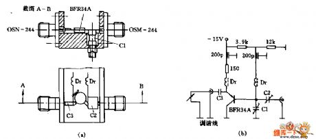
The 4GHZ oscillator circuit is as shown:
(View)
View full Circuit Diagram | Comments | Reading(781)
Phase sequence detection circuit
Published:2011/4/28 18:50:00 Author:Christina | Keyword: Phase sequence, detection
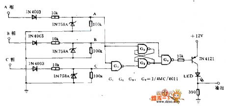
If the motor of the drive pump, compressor or transmission belt reverse run, the equipment will be damaged. This circuit can find out whether the motor phase sequence is error, and protect the motor damaged by the rapid-heating. When the phase sequence is correct, the LED lights. When the phase sequence is not correct, the output power goes low, the LED not lights. The diode and zener convert the sine wave into rectangular logic level pulse. when the phase sequence is correct, G4 outputs a string of rectangular pulse, the pulse width is about 2.5 ns. When the phase sequence is not correct, the output power is zero. The output pulse edge's zero-crossing and B phase's zero-crossing are synchronous, so the output pulse can be used to trig the SCR and drive relay coil which are connected with the Phase B's two ends. This kind of SCR can supply power to relay only when the phase sequence is correct.
(View)
View full Circuit Diagram | Comments | Reading(9589)
TC9OA49P-I2C bus control A/D, D/A and the comb filter integrated circuit
Published:2011/4/28 1:42:00 Author:TaoXi | Keyword: bus control, A/D, D/A, comb filter
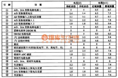
The TC9OA49P is one kind of bus control A/D, D/A and the comb filter integrated circuit that is produced by the TOSHIBA company, it can be used in all brands of new large screen color TV, the pin functions and data is shown as table 1. This data is from the Changhong CN-15 color TV.
Table 1 The pinfunctionsanddata of the TC9OA49P (View)
View full Circuit Diagram | Comments | Reading(489)
Cardiogram amplifying circuit
Published:2011/4/2 4:24:00 Author:may | Keyword: Cardiogram amplifying
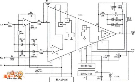
Cardiogram amplifying circuit is shown in the diagram:
(View)
View full Circuit Diagram | Comments | Reading(558)
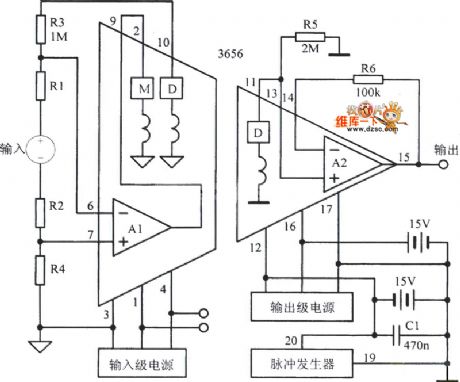
Isolation amplifier 3650 circuit
Published:2011/4/2 4:24:00 Author:may | Keyword: Isolation amplifier
Isolation amplifier 3650 circuit is show in the following diagram:
(View)
View full Circuit Diagram | Comments | Reading(742)
Positive and negative 120V Output amplifier circuit
Published:2011/4/2 4:09:00 Author:may | Keyword: amplifier, positive, negative, 120V output
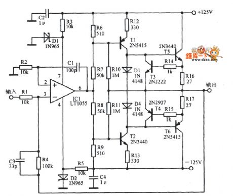
Positive and negative 120V Output amplifier circuit is shown in the following diagram:
(View)
View full Circuit Diagram | Comments | Reading(1692)
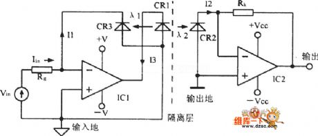
Isolation amplifier circuit with folating signal source differential input
Published:2011/4/11 2:57:00 Author:may | Keyword: Isolation amplifier, folating signal, source differential input
Isolation amplifier circuit with folating signal source differential input is shown in the following picture:
(View)
View full Circuit Diagram | Comments | Reading(783)
An amplifier circuit with 50KHz bandwidth
Published:2011/4/6 5:40:00 Author:may | Keyword: 50KHz bandwidth, amplifier
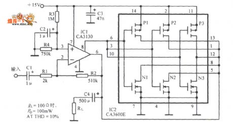
An amplifier circuit with 50KHz bandwidth is show in the following diagram:
(View)
View full Circuit Diagram | Comments | Reading(715)
915MHz RF amplifier circuit composed of RF2103P
Published:2011/4/11 2:36:00 Author:may | Keyword: RF amplifier
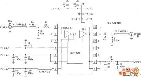
The picture is 915MHz RF amplifier circuit composed of RF2103P. P1 is socket, among which, P1-1 connect power Vcc, P1-2 connect ground, P1-3 connect power down control voltage VB; J2 is RF output socket.
(View)
View full Circuit Diagram | Comments | Reading(985)
Isolation amplifier circuit composed of ISO100 and photod
Published:2011/4/11 2:58:00 Author:may | Keyword: Isolation amplifier, photod
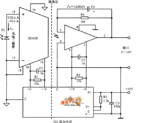
Isolation amplifier circuit composed of ISO100 and photod is shown in the diagram:
(View)
View full Circuit Diagram | Comments | Reading(659)
The circuit diagram of electric fan adding breeze gear by capacitance
Published:2011/4/11 3:43:00 Author:may | Keyword: electric fan, adding breeze gear, capacitance
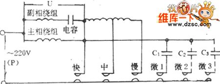
The circuit diagram of electric fan adding breeze gear by capacitance is shown in the following diagram:
(View)
View full Circuit Diagram | Comments | Reading(535)
300B Vacuum Tube Single End A Type Power Amplifier Circuit
Published:2011/4/23 1:00:00 Author:May | Keyword: Vacuum Tube, Single End, A Type, Power Amplifier
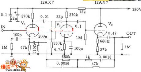
300B Vacuum Tube Single End A Type Power Amplifier Circuit, vacuum tube has 12AX7 pdf. The frequency respondence of this amplifier is very flat, it only has ±1dB changefrom 18Hz~30KHz, total harmonic distortion of this amplifier is less than 1%. (View)
View full Circuit Diagram | Comments | Reading(3185)
Using LM386 as Kara OK muffler circuit diagram
Published:2011/4/28 1:25:00 Author:Rebekka | Keyword: Kara OK muffler
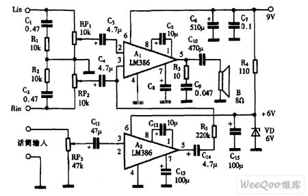
Using LM386 as Kara OK muffler circuit diagram is shown as above. (View)
View full Circuit Diagram | Comments | Reading(2179)
Multipurpose Exposure Timer Circuit
Published:2011/4/27 18:40:00 Author:Christina | Keyword: Multi-exposure, Exposure Timer
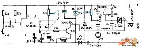
The device can satisfy the photographers to master the appropriate exposure to ensure the quality of photos. This device has many features such as accurate timing, wide-ranging application, exposure timing, dimming.etc. Bulb of enlarger or Electric irons, electric blankets, lamps, electric fans and motors can be connected to the output sockets CZ, the output power limited by the capacity of SCR, if it is a pure resistive load, this device can provide 600W of output power; if it is capacitive or inductive load, the output power is less than 300W.
(View)
View full Circuit Diagram | Comments | Reading(615)
Weak Light Measurement Circuit
Published:2011/4/27 18:41:00 Author:Christina | Keyword: Weak Light, Measurement
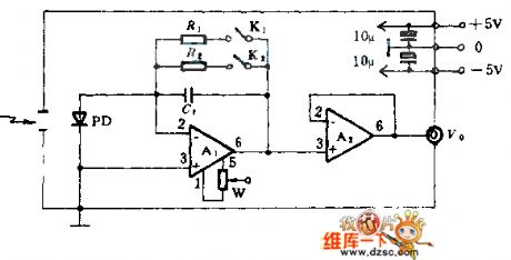
The PD in this figure is one kind of photodiode such as S1226,S1336,S2386.etc (produced by the Hamamatsu Corporation), A1 is the operational amplifier, model can be the AD515,OPA111,OPA128.etc; A2 is the operational amplifier OP-07; capacitor (C1) can use the 10 to 100pF burning polystyrene capacitor; feedback resistor R is the metal glaze resistor, the maximum is 10GΩ; K is the low-leakage relay. The whole circuit is in the metal shield box, the shield box and the circuit ground is connected. In the figure, W is the pioneer 0 circle precision potentiometer.
(View)
View full Circuit Diagram | Comments | Reading(717)
lm4766+ne5532 package 2x40w amplifier circuit
Published:2011/4/27 20:59:00 Author:Christina | Keyword: lm4766+ne5532 package, 2x40w amplifier
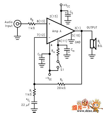
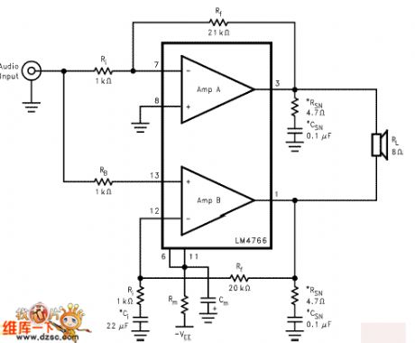
The following figure is the typical application circuit of this ic (btl mono)
In the first stage amplifier, by change the ratio of r3/r2, you can change the first stage magnification. User can reset the source of sound by the actual situation, usually between 1-10 times.
The power supply section uses the current and voltage integrated dynamic feedback circuit, this circuit has two advantages, for details, please see the related website of the tda7293/lm3886.
The power supply section uses the three-terminal voltage regulator power supplier, r18/re18 is the current limit resistor (10 to 30 ohm), c9/ce9 is the 6800/35v large reservoir capacitors, power supply decoupling small capacitor is 0. 1u is the cbb capacitor of wima.
The lm4766 has the warm tone, similar to the tube amp tone and the lm1875, but the power of lm4766 is larger than lm1875, I think it is the upgrade of lm1875, that's why it is the most popular ic of the music fans. Especially the friends who like the sound of lm1875. (View)
View full Circuit Diagram | Comments | Reading(7015)
Antivibration Circuit Equipped NAND Gate
Published:2011/4/25 23:57:00 Author:Joyce | Keyword: Antivibration, Equipped with, NAND Gate

Dither signals may be arised when the mechanical switch of the keyboard is turned into digital signals,which would lead to incorrect operation , in this case, you can refer to this circuit. Under the condition of using irregular flip-flop (Q1 = Q2 = 0),you can connect a piece of ground wire with the rest of the NAND gates.
(View)
View full Circuit Diagram | Comments | Reading(548)
Circuit Diagram of 555 Economy Fluorescent Display Filament Voltage Supplier
Published:2011/4/26 18:32:00 Author:Christina | Keyword: Economy, Fluorescent Display, Filament Voltage
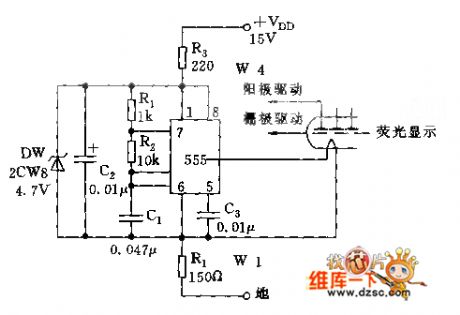
Most fluorescence filament code tubes of the calculator need to add the 6V DC and the several KHZ AC voltage (VP-P voltage), this circuit can meet the requirement.
As shown, 555 and R1, R2, C1form the astable-multivibrator, the oscillation frequency f=1.44/(R1+2R2), C1 is about 4KHZ. And the DC bias of the filament is VDD·R4/(R3+R4)≈6V.
Welcome to reprint, the information is from the Weiku Electronic Market Network (www.dzsc.com). (View)
View full Circuit Diagram | Comments | Reading(835)
Long-Time Disconnect Delayer Circuit
Published:2011/4/22 4:26:00 Author:Christina | Keyword: Long-Time Disconnect, Delayer Circuit
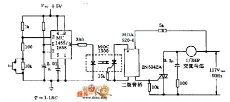
If we combine the timer 555, optical isolator 1300 and the bridge trigger triac switch, and press the control switch to supply power to the AC motor or other devices for 1h, timer(2)'s voltage will be less than 1/3Vcc, the timer output power become high, so the LED turn-on. At the same time, the capacitor of (7) starts charging, and before the voltage is 2/3VCC, output power is still high; when the output power back to low, turn off the motor.
(View)
View full Circuit Diagram | Comments | Reading(1587)
Frequency deviation measurement Circuit
Published:2011/4/26 18:37:00 Author:Christina | Keyword: Frequency deviation measurement
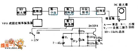
This circuit uses the same simple crystal oscillator and oscilloscope of carrier frequency deviation from center frequency with the fixed or adjustable FM receiver. The vertical amplifier of the oscilloscope uses the direct couple mode. To calibrate the tuned oscillator and display the figure higher than the receiver's second vibration 10KHZ or lower than the receiver's second vibration 15KHZ, we need to calibrate the oscilloscope screen. Because the transmitter's frequency is equal in the two channels, so we just need to adjust one oscilloscope.
(View)
View full Circuit Diagram | Comments | Reading(576)
| Pages:236/250 At 20221222223224225226227228229230231232233234235236237238239240Under 20 |
Circuit Categories
power supply circuit
Amplifier Circuit
Basic Circuit
LED and Light Circuit
Sensor Circuit
Signal Processing
Electrical Equipment Circuit
Control Circuit
Remote Control Circuit
A/D-D/A Converter Circuit
Audio Circuit
Measuring and Test Circuit
Communication Circuit
Computer-Related Circuit
555 Circuit
Automotive Circuit
Repairing Circuit