
Index 232
Gaoshi AV9093 amplifier control and display circuit diagram
Published:2011/5/4 9:08:00 Author:Nancy | Keyword: Gaoshi, amplifier, control and display
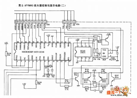
(View)
View full Circuit Diagram | Comments | Reading(620)
TDA7266 two-channel audio power amplifier integrated circuit diagram
Published:2011/5/4 3:08:00 Author:Ecco | Keyword: two-channel , audio, power amplifier, integrated circuit
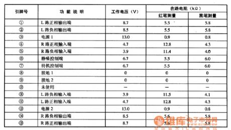
TDA7266 is the two-channel audio power amplifier integrated circuit produced by Philips, it is widely used in hi-fi system, such as TV audio, home theater, multi-media off audio, car audio and so on. 1. The features of functionsTDA7266 integrated circuit includes two identical audio power amplifier circuit, the squelch control circuit, the standby control circuit, and overheat protection and short circuit protection circuit. 2. Pin functions and data TDA7266 IC uses package with 15 pin in single row, the pin functions and data are listed in Table 1. Table 1 TDA7266 shows integrated circuit pin functions and data.
(View)
View full Circuit Diagram | Comments | Reading(3253)
TDA7264, TDA7264A AB two-channel audio power amplifier integrated circuit diagram
Published:2011/5/4 3:16:00 Author:Ecco | Keyword: AB , two-channel , audio, power amplifier, integrated circuit
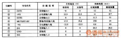
TDA7264, TDA7264A are the two-channel AB audio power amplifier integrated circuits produced by Philips, it is widely used in large screen color television with HID projection. 1. The features of functions TDA7264A is an improved product of TDA7264, the difference is only a few parameters, and other functions and pinout are exactly the same. The inter sets the mute switch, overvoltage and overtemperature protection, and its working voltage can reach 50V, the output power of per channel is 25W. 2. Pin functions and data TDA7264, TDA7264A uses 8-pin package in single row, the pin function and the data are shown in Table 1. Table 1 shows TDA7264A integrated circuit pin functions and data.
(View)
View full Circuit Diagram | Comments | Reading(1635)
TDA7263AM, TDA7263M two-channel audio power amplifier integrated circuit diagram
Published:2011/5/4 3:22:00 Author:Ecco | Keyword: two-channel, audio , power amplifier, integrated circuit
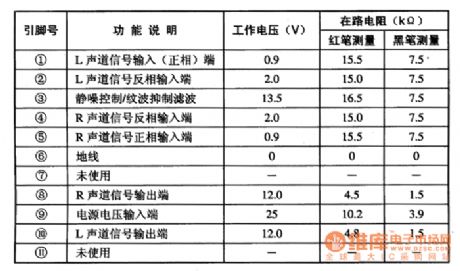
TDA7263M is the two-channel audio power amplifier integrated circuit produced by Philips, it is widely used in Haier, Konka series of large-screen color TV. 1. The features of functions TDA7263M IC includes two power amplifier circuits with the same functions, squelch control circuit, over-cooked and short circuit protection circuit. Per channel output power is 8W. 2. Pin functions and data TDA7263M IC uses 11 pin single in-line package, the pin functions and data are listed in Table 1. Table 1 shows TDA7263M pin function and data.
Note: The main difference between TDA7263AM and TDA7263M is that the functions of output power and pin ③ are different. (View)
View full Circuit Diagram | Comments | Reading(1090)
RF2162 900MHz linear amplifier pin circuit
Published:2011/5/3 2:49:00 Author:May | Keyword: 900MHz, linear amplifier
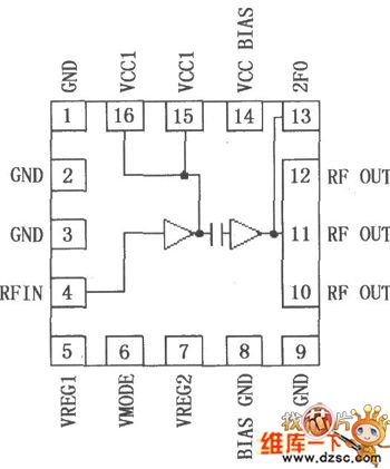
FR2612 is a high power, high efficiency linear amplifier IC which is applied to 3V handheld systems. It is treated by advanced gallium heterostructure bipolar transistor (HBT). It is designed for finnal linear RF amplification of double mode 3V CDMA/AMPS handheld digital type celluar system equipment, band spread system and other applictions with 800~960MHz working frequency. RF2162 has a analog bias control voltage to generate largest efficiency. The device itself contains 50Ω input and output. It is very easy to match best power, efficiency and linear characteristic. RF2162 adopts compact sixteen pins non-leaded package. Its pin array is shown in the diagram.
(View)
View full Circuit Diagram | Comments | Reading(761)
880MHz Low Noise Amplification Application Circuit Composed Of RF2347
Published:2011/5/3 20:00:00 Author:Robert | Keyword: 880MHz, Low Noise, Amplification, Application
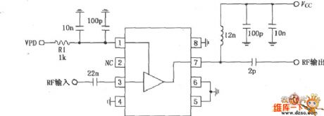
This pictureshown below is the 880MHz low noise amplification application circuit composed of RF2347. The RF signal is inputed to the 3 foot, and is outputed from 7 foot after amplification in the amplifiers. The 3 footis directly coupled with the internal amplifier, so a 22pF block-DC coupling capacitor is added outside the 3 foot, and therelated resistance would be 50Ω when working at 836MHz. The 7 foot is the output port of the open collector electrode, which can be connected to power Vcc through choke coil or matching inductor. This foot's typical matching resistance is 50Ω, and can be connected to external output-matching networks to suit the amplifier's output resistance, so that can get the maximum output power and efficiency. The 1 foot is for power down control terminal, which is used to control the drift current. When VPD=(2.8±0.1)V (Typical IPD is 8.5mA) the circuit begins to work; when VPD<0.9V the circuit becomes closed; VPD reqiures external RF bypass circuit.
(View)
View full Circuit Diagram | Comments | Reading(580)
Input status indication circuit
Published:2011/5/3 6:53:00 Author:Christina | Keyword: Input status, indication
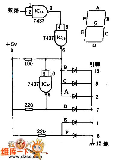
This circuit monitors the bit data input, and shows H or L on the 7-segment digital display by the conditions. This circuit uses two 7437 inverters and one DL-704 LED common cathode. The diode symbol means one segment of the digital tube (when segment A displaying H or L , the diode symbol means nothing). The 7437 inverter's power connection are: (14) connects to +5V, (7) connects to ground.
(View)
View full Circuit Diagram | Comments | Reading(659)
Measuring small current amplifier circuit diagram
Published:2011/5/4 1:40:00 Author:Rebekka | Keyword: Measuring small current amplifier
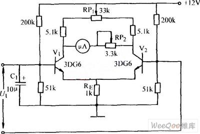
Measuring small current amplifier circuit diagram. (View)
View full Circuit Diagram | Comments | Reading(593)
The simplest voice FET amplifier board circuit
Published:2011/5/3 6:30:00 Author:Christina | Keyword: simplest voice, FET, amplifier board
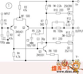
The Hitachi MOS FET amplification has the sound Of nature, and it is used by many of the top machine. The writer use the Hitachi 2SK399, 2SJ113 high-power tube (cheap and easy to purchase, common) to weld a minimalist amplifier, the circuit is simple that has only 23 components. This circuit has the good price and it is worth to recommend.
In the figure, Q1~Q3 use the 2N5401, 2N5551 (TV video amplifier tubes) as the differential and the main voltage amplification, because it has good frequency characteristics, good linearity and good effect. These amplification tubes can also choose the special fever tube, the sound quality can be further improved.Production requirements: the difference tube and the power tube should be matched to improve the open loop linear and improve the quality. HFEs' difference of Q1 and Q2 is ≤5% when the current is 0-5mA, higher HFE is better. The resistor uses the metal film resistor. In figure 1, you adjust the W1 to make the output mid-point be zero. This circuit can increase the output power by adding the output tube or increase the supply voltage. When it is ±36V, 8Ω, the output power is 50W. (View)
View full Circuit Diagram | Comments | Reading(2877)
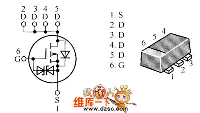
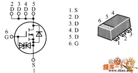
H7N0310LM Internal Circuit
Published:2011/5/3 9:31:00 Author:Felicity | Keyword: Internal Circuit
The picture above shows the H7N0310LM Internal Circuit. (View)
View full Circuit Diagram | Comments | Reading(409)
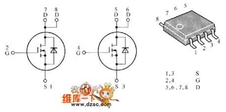
HAT1054R Internal Ciecuit
Published:2011/5/3 9:31:00 Author:Felicity | Keyword: Power Amplifier Circuit,

The picture above shows the HAT1054R Internal Circuit. (View)
View full Circuit Diagram | Comments | Reading(426)
TDAI512 End-Stage Amplifier Circuit
Published:2011/5/3 9:40:00 Author:Robert | Keyword: End-Stage Amplifier
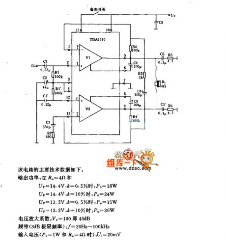
TDAI512 End-Stage Amplifier Circuit is shown below. This circuits main technical data is listed here:
Output power, at RL=4ohms and
when Up=14.4V, k=0.5%, Po=18W;
when Up=14.4V, k=10%, Po=24W;
when Up=13.2V, k=0.5%, Po=15W;
when Up=13.2V, k=10%, Po=20W.
The amplification factor of voltage is Vu=100, which also means 40dB.
Bandwidth (3dB limit frequency): f=20Hz to 100KHz
Input voltage (Po=1W and RL=4ohms): Ui=20mV.
(View)
View full Circuit Diagram | Comments | Reading(557)
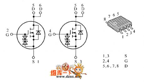
HAT1043M Internal Circuit
Published:2011/5/3 8:30:00 Author:Felicity | Keyword: Internal Circuit
The picture above shows the HAT1043M Internal Circuit. (View)
View full Circuit Diagram | Comments | Reading(460)
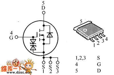
HAT1089C Internal Circuit
Published:2011/5/3 8:26:00 Author:Felicity | Keyword: Internal Circuit

The picture above shows the HAT1089C Internal Circuit. (View)
View full Circuit Diagram | Comments | Reading(520)
HAT1093C Internal Circuit
Published:2011/5/3 8:21:00 Author:Felicity | Keyword: Internal Circuit

The picture above shows the HAT1090C Internal Circuit. (View)
View full Circuit Diagram | Comments | Reading(456)
HTA1094C Internal Circuit
Published:2011/5/3 8:17:00 Author:Felicity | Keyword: Internal Circuit
The picture above shows the HTA1094C Internal Circuit. (View)
View full Circuit Diagram | Comments | Reading(414)
HAT2057RA Internal Circuit
Published:2011/5/3 7:57:00 Author:Felicity | Keyword: Internal Circuit
The picture above shows the HAT2057RA Internal Circuit. (View)
View full Circuit Diagram | Comments | Reading(457)
HAT2108R、HAT2093R Internal Circuit
Published:2011/5/3 7:45:00 Author:Felicity | Keyword: Internal Circuit,
The picture above shows the HAT2108R、HAT2093R Internal Circuit. (View)
View full Circuit Diagram | Comments | Reading(444)
HAT2134H、HAT2160H Internal Circuit
Published:2011/5/3 7:43:00 Author:Felicity | Keyword: Internal Circuit,
The picture above shows the HAT2134H、HAT2160H Internal Circuit. (View)
View full Circuit Diagram | Comments | Reading(456)
HAT2206C、HAT2207C、HAT2221C、HAT1108C Internal Circuit
Published:2011/5/3 7:09:00 Author:Felicity | Keyword: Internal Circuit,
The picture above shows the HAT2206C、HAT2207C、HAT2221C、HAT1108C Internal Circuit. (View)
View full Circuit Diagram | Comments | Reading(434)
| Pages:232/250 At 20221222223224225226227228229230231232233234235236237238239240Under 20 |
Circuit Categories
power supply circuit
Amplifier Circuit
Basic Circuit
LED and Light Circuit
Sensor Circuit
Signal Processing
Electrical Equipment Circuit
Control Circuit
Remote Control Circuit
A/D-D/A Converter Circuit
Audio Circuit
Measuring and Test Circuit
Communication Circuit
Computer-Related Circuit
555 Circuit
Automotive Circuit
Repairing Circuit